Finding Suspension Roll and Pitch Centres
The trouble with suspension roll centres is that they’re often rather obscure in concept, let alone in location.
In this article I tried to simplify the concept of roll centres, largely by using geometric drawings.
(So what actually is a roll centre? It’s the imaginary point about which the car rolls. The front and rear suspension roll centres can be at different heights above the ground [but always on the centreline of the car] and on different vehicles the heights can vary from being above the ground, to at ground level, to below the ground.)
Normally roll centres are located by careful drawings of the suspension, a prerequisite being that you need to know the exact location of suspension pivot points, lengths of suspension arms and so on.

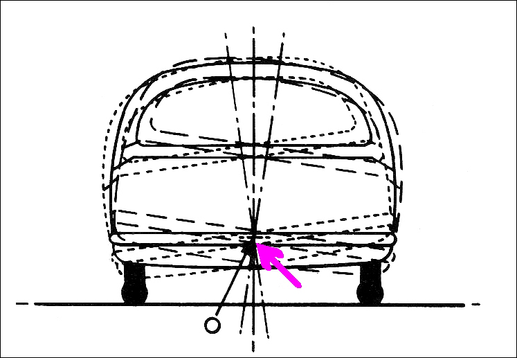
However, as shown in this diagram, the roll centre of an existing vehicle can be located by directly measuring the way the car behaves. If the car is physically rolled from side to side, there will be one point that never moves (or moves only minimally). That’s the roll centre. If multiple photos are taken of the car in end-view, this point can be easily located.
This is a very useful technique – you can locate the roll centres for either the front or rear suspension, and no difficult measurements of the suspension geometry need be made.
And it’s not just the roll centre(s) that can be located in this way. In addition to roll, cars pitch – that is, the front dives and the rear rises, or vice versa. This occurs not only under acceleration and braking, but also over bumps in the road. The amount of pitch – or, more precisely, the pitch accelerations – are a major determinant of ride quality.
So how do you find the pitch centre? A book I have – Fundamentals of Vehicle Dynamics by Thomas Gillespie – devotes a number of pages of mathematics to locating the pitch centre of a car. However, as with the roll centre, pitch centres can be found by direct measurement.
I did this the other day for my recumbent, pedal, suspension trike. I am doing a lot of work on its suspension, including measuring real-time pitch accelerations over bumpy surfaces. After making a host of measurements of these accelerations, I thought I should find where the pitch centre actually is.
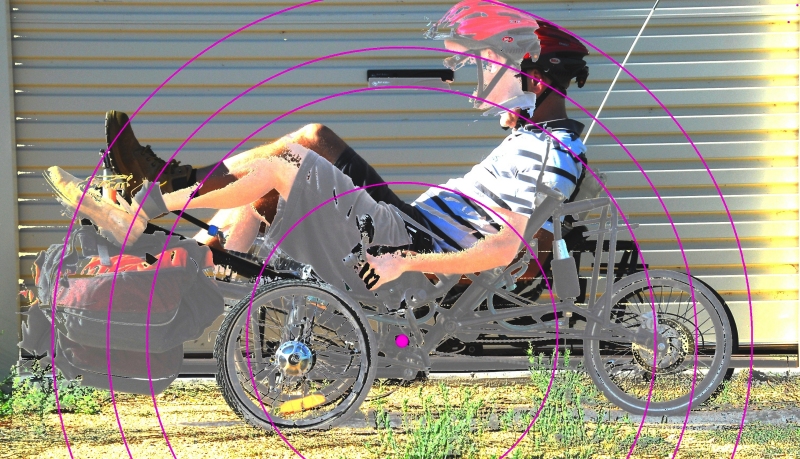
I had two photos taken of the trike (with me on it), both in side view. In one pic, the front suspension was at max extension and the rear in max compression. In the other pic, the suspension extensions were the other way around. (I use air suspension and for this test I interconnected the units front to back, so giving zero resistance to pitch. To get the front to adopt max compression, I added some weights.)
I then overlaid the pics, playing with the image until I could find a point around which the trike body was rotating in pitch. This was best shown by placing radii centred on that point – the circular lines intersect with the same part of the trike in both pitch extremes. (It’s harder to explain than it is to do!)

In this pic, the pink dot is the pitch centre. As can be seen, the greatest mass on the machine (that’s me) is located above the pitch centre. Furthermore, a lot of that mass is located a fair way from the pitch centre, increasing the pitch moment of inertia. This is one reason that over rough ground, the pitch accelerations of the machine are very low.
Talking about moments of inertia in pitch is taking it a further step in complexity. But back to ‘centres’ – if you’re grappling with the suspension design of a custom vehicle, it make things a lot clearer when you can so easily locate not only the roll centres, but also the pitch centre.

 Julian Edgar, 50, has been writing about car modification and automotive technology for nearly 25 years. He has owned cars with two, three, four, five, six and eight cylinders; single turbo, twin turbo, supercharged, diesel and hybrid electric drivelines. He lists his transport interests as turbocharging, aerodynamics, suspension design and human-powered vehicles.
