Suspension

Posted on June 4th, 2015 in Opinion,Suspension by Julian Edgar

I think that suspension design is one of the most complex areas of automotive engineering. I am not thinking here about just spring and damper rates – but those are of course hugely complex in themselves – but of changes that occur through suspension movement.

For example, a wheel experiencing bump and rebound is likely to have a designed-in change in its camber – going into negative camber when in bump. This helps keep the wheel more upright when the body rolls in cornering (or at least the outside, most important, wheel anyway).

But what about something like anti-dive geometry? This set of suspension angles causes the car’s front springs to resist compression when the car is being braked.

So how does this work? Imagine a very simple front suspension system with a leading arm per wheel – an arm that runs longitudinally to support the wheel. (A Citroen 2CV is the only car I know of with this approach, but that’s OK.) The brake is mounted on the wheel, so the torque loads of the brake are fed back through the suspension arm.

The car drives along, and then the brakes are applied. The brake load causes the longitudinal suspension arm to try to rotate around the wheel, so applying an upward force on the suspension pivot. This prevents that end of the car from compressing its springs as much – more of the car’s weight is being dynamically taken via the suspension pivots than through the springs.

The result is that the car dives less under brakes.

Now as mentioned, not many cars have longitudinal suspension arms, so this arm is often actually virtual, being in effect created by (for example) the front wishbone mounts not being parallel when viewed from the side. If they form an angle that converges towards the rear of the car, anti-dive will occur.

So anti-dive sounds great… but there are also downsides.

Under brakes, the car does not behave as many expect it to – it doesn’t dip its nose as much.

Under brakes, the suspension is less springy – more of the weight (and so vertical acceleration of bumps) is fed through the suspension pivots and not the springs.

Under brakes, in many cases the geometry is such that the wheel moves forward, so meeting bumps more harshly. (And there’s already a higher effective spring rate, remember.)

And it goes on: under brakes and when hitting a bump, the steering geometry (eg castor) may not adopt the same angles as would normally occur if anti-dive were not present… so the car may react to bumps differently when being braked.

So should anti-dive not be used? No – in cars with soft suspension and a high centre of gravity, it can be very effective.

But then again, the amount of brake dive also depends in part on the stiffness of the slow-speed bump damping provided by the shocks.

You see? Every aspect relates to another aspect: not one suspension design criterion can be viewed in isolation.

It’s all very complex….

Sprung and unsprung weight natural frequencies

Posted on May 10th, 2015 in Suspension,testing by Julian Edgar

My major job – training people in business and government writing skills – takes me all over the country. Usually that involves lots of flights, but recently I chose to take the Greyhound bus between Coffs Harbour and Port Macquarie.

The bus travel was actually very pleasant – though I didn’t envy the driver threading his way through the dusk traffic on narrow roads constrained by constant roadworks.

When I was sitting in the bus, I started analysing its ride quality over the often poor road surfaces.

To cope with the large variation in possible load while still giving the best ride quality, long-distance buses typically use air suspension. (This also lets the bus ‘kneel’ as people get on and off.)

The air suspension stiffness is set to give a natural frequency of about 1Hz – the best frequency for ride quality.

And, in the bus, the ride felt about right for a 1Hz natural frequency – the absorption of large bumps was superb.

However, sitting back and admiring the flowing scenery outside the window, I thought I could feel another ride quality characteristic – and this one was not so pleasant.

Superimposed on the soft suspension movements was a higher frequency judder. It was like riding in a conventional car travelling on a road that had long wavelength bumps – but a corrugated surface.

Rather than guess any longer, I whipped out my iPhone and, using the ‘Vibration’ app, recorded the ride accelerations being experienced by the bus body. The seat next to me was empty and so I put the phone down on the cushion and gently held it in place.

Ten seconds later I had a record, and a moment after that I used the software to perform a Fourier analysis, giving the dominant frequencies in the waveform.

This showed a peak at 1Hz (the air springs) but also another peak at about 10Hz. The latter was the juddering “corrugations” I could also feel.

But what was causing this higher frequency of vibration?

The higher speed juddering was caused by the natural frequency of the unsprung mass – the weight of the suspension acting on the “springs” that comprise the tyres.

But it gets more complex. How do the 10Hz unsprung weight vibrations get through the 1Hz air spring isolation? With the forcing frequency (10Hz) so far from the natural frequency (1Hz), wouldn’t the transmission be almost zero?

I am not completely sure, but I think it has to do with the massiveness of the unsprung weight. Was that rapid shaking of the huge tyres and suspension arms feeding a vibration through the suspension mounts that I could feel?

Reflecting on this, I realised that I’d felt all this before – but to a lesser degree. In 4WD passenger cars using solid front and rear axles (ie a high unsprung:sprung mass ratio) you can feel something similar… it’s a bit like the car is being shaken by the suspension. So the soft main springing was being subverted in ride quality by the high unsprung weight bouncing on the tyres.

Here’s another point: dampers need to control suspension movement at both the suspension and tyre natural frequencies…. but the requirements for controlling each mode are quite different. One requires damping of large amplitude, low frequencies (the movement on the body springs) – and the other damping of high frequency, low amplitudes (the movement on the tyre springs).

It would be interesting to talk to a damper manufacturer about the decisions in damper design that they must be making.

Bits from all around the world

Posted on August 16th, 2014 in Materials,Opinion,Suspension,Technologies,Turbocharging by Julian Edgar

I’ve written before about the enormous range of automotive parts now available through eBay, but until I have been working on my little Honda, I’d never realised how well developed such a part-sourcing network it now is.

As I write this morning, I am watching the tracking on my DHL express package that contains the stainless steel gasket set for my turbo. The package, in the last three days, has been through five countries. It started off in Latvia, went then to Lithuania before reaching Germany. Then it travelled to Heathrow airport in London, before arriving (this morning at 2.20 am) in Sydney. Out in country New South Wales, I reckon I’ll get it in the next few days.

And the exhaust gaskets are not alone in having travelled far.

My Bosch fuel pressure regulator came from the US, the fuel rail adaptor from the UK. Also from the UK came carbon fibre sheet for making a new dash panel, and replacement ignition coils. Other stuff direct from the US has included oil temperature and pressure sensors, the boost control solenoid and a water/air intercooler pump.

From China there has been a host of parts – the front-mount radiator for the water/air intercooling system, fittings, hose clamps, hose joiners and rubber grommets. On its way now from China are a thermocouple adaptor board, a weld-on bung for the thermocouple, and the thermocouple itself.

And of course I have bought plenty of parts locally.

With the fast availability of parts, cheaper than ever before, from all around the world, there’s never been a better time to be modifying cars…

Wrecking yards are better than ever!

Posted on August 8th, 2014 in Engine Management,Materials,Opinion,Suspension,Turbocharging by Julian Edgar

I’ve always loved going to car wreckers, looking at the bits and pieces available so cheaply and wondering how I can integrate them into my car.

I started visiting wreckers when I had my first car – a 1973 Honda Z. That was way back in the early Eighties. I remember looking through the field of dismembered wrecks, finding dash parts from Honda Civics that I could shoehorn into the Z. I even integrated the high beam flash stalk from a Datsun 260Z into the little Honda.

Time passed, and I was then looking at wreckers importing Japanese engines and transmissions…. That led to a turbo 660cc 3-cylinder engine going into my Daihatsu Handi, and later an RB20DET turbo six going into a C210 Skyline.

I have been musing over this because in the last month I’ve been spending a lot of time back in wrecking yards.

I’m lucky enough to have discovered a wrecker of the old school, one that lets you wander around the yard of cars, spanner and pliers in hand, able to take off whatever parts you want and then take them to the front counter to have them priced.

But the big difference now is this: with modern hi-tech cars having been around for literally decades, the sheer variety of the parts that you can buy is amazing.

Need an idle speed control valve (as I did the other day)? Well, at this yard you can chose between Bosch (three types), Nissan, Toyota, Holden, Ford, Mazda – basically, every car in the yard has an idle speed control valve!

After half an hour of browsing, I walked out with a Bosch idle speed control valve from a BMW, complete with plug and a short section of loom. Cost? AUD$33.

Need a factory bracket on which to mount a GM MAP sensor? Sure – look under the bonnets of not only GM cars but also Daewoos. Cost? In this case, I was charged nothing!

Want some direct fire ignition coils? Would you like those coil-on-plug or remote-mounted? After a long look, I decided instead to go brand new with some Bosch coils – but the browse through the yard showed some very interesting approaches.

Need some 19mm hoses, preformed with bends to plumb a turbo blow-off valve? An hour later I walked out with no less than nine of them – all different lengths and bend radii. Cost? AUD$11. Oh yes, and that also included a rubber mount for the idle speed control valve that I’d forgotten to get earlier!

If you’ve not been to a wrecking yard for a long time, find a good one and have a long look around. You might be as surprised as I was.


Getting enough clearance

Posted on May 30th, 2014 in Driving Emotion,Safety,Suspension,testing by Julian Edgar

When is enough clearance sufficient?

If you’ve modified a lot on cars, you’ll have come across this question. It might be the clearance between the exhaust the bodywork, clearance of a driveshaft at full suspension bump with a chassis member or subframe, or even clearance between a large turbo and bodywork.

Years ago I read an excellent book written by an automotive suspension engineer working in the 1950s. In it he made the (almost throwaway) line that there’s no need to provide tyre clearance at full suspension bump AND full steering lock – the idea being that this situation almost never occurs, and if contact did in fact occur in that situation, the car would be moving so slowly that it wouldn’t matter much anyway.

These thoughts are intruding because at the moment I am massaging a turbo dump pipe so that it clears a steering tie-rod, with the greatest potential conflict occurring at full suspension droop and with full right-hand steering lock.

At full droop but with the wheels pointing straightahead – no problem. And at full steering lock and with the wheels at normal ride height – again no problem.

It’s just at that particular combination – one that again is very unlikely to ever occur – that I have the issue.

I am concerned because if the car has to undergo full engineering approval, I can just imagine an engineer saying something along the lines that conflict should not be able to occur at ANY combination of lock and suspension movement….

And even if clearance is achieved, how much clearance is enough? If I were ornery enough to throw in maximum engine torque reaction movement at just that moment, perhaps another 10mm of clearance would be needed.

But hold on! How could the engine be developing maximum torque if the suspension is at full droop? After all, in that situation there’s very little – next to none in fact – of the car’s weight on the tyre… so how could it transmit the torque anyway? No torque transmission means no transverse engine rocking!

Hmm, what about if the car has an LSD, and a very stiff front anti-roll bar, and is cornering hard enough (at full lock!) to lift a wheel? Then I suppose one could imagine a situation where something like contact could occur.

Aaaagh!

Doing only half the job

Posted on August 2nd, 2012 in Opinion,Suspension by Julian Edgar

The function of the suspension is to allow tyres to follow the ups and downs of the roads, while at the same time the car’s body movement doesn’t replicate those ups and downs.

However, if that was all that was needed, a very soft suspension would achieve these aims very well – but the car would handle poorly. So the first two points subsequently need to be modified to achieve competent handling.

And for decades – perhaps eight or nine of them – this was the way in which suspension development in cars occurred. Cushioning occupants was primarily about spring rates; maintaining tyre contact was about damping; and achieving good handling was about dynamic wheel location, roll centre height and roll stiffness.

The trouble is, to my way of thinking, in the last decade or so that whole approach has gone out the window. The approach is now:

(1) gain best handling

(2) refine system to provide acceptable ride comfort

Now let me say loud and clear: in sporting cars that’s fine.

But in all cars?

How stupid.

Let’s put all this a different way. Pick a car from 30 years ago and pitch it in a handling contest against the current equivalent. Yep, the current car will win. Now fit the old car with low profile and wide rubber, massively stiffen its springs and damping and anti-roll bars – and I’d suggest that the old and new will now be very close in handling….as measured on real roads.

I’d argue those designers of that 1980s car could have had similar handling if they’d chosen to degrade ride comfort in the way of current cars.

But this is not a blanket condemnation of modern car technology. Electronic stability control is a fantastic handling innovation. All-wheel drive with variable torque direction is a fantastic handling innovation. Electronically-controlled power steering is a fantastic handling innovation (“handling”, because it allows higher degrees of castor, and so greater negative dynamic camber addition). Multi-link suspension systems and variable direction suspension compliance are fantastic handling innovations.

It’s not the current technology: it’s the current philosophy.

The outcome is rather bizarre. There are now many people who have never been in a car that rides well. They have no knowledge of what is possible: they simply believe that all cars ride in a manner in which in the past only trucks rode.

Recently I drove a diesel sedan from a car yard. The ride, factory standard, was so harsh I could hear my wife’s voice changing as air was forced out of her lungs by the bumps. Just in a normal suburban area of an Australian city. I took the car back.

“I won’t buy this,” I said, “the ride is so harsh.”

The young salesman’s face contorted in genuine disbelief. “How do you figure that?” he asked incredulously.

Clearly, he had never been in a car with a good ride.

It’s a bit like people who have listened to only MP3s played through tiny speakers. They have literally no idea of what good sound is like.

So what would be logical reasons that current car designers have chosen to degrade ride comfort at the expense of handling?

Oh, well speed limits have gone up hugely over the last 20 years, so better handling is needed to cope.

And another: the enforcement of driving behaviour is so much less rigorous than it once was, so everyone can now punt their cars hard on the road.

And a final: all roads are now so well surfaced that the poor roads of 20 or 30 years ago are now gone.

But not one of these is true!

Cars with suspension set up for smooth race tracks (or to put this another way, set up so that they get good media reviews from young, single, performance car drivers) are silly for general road use.

These days, the vast majority of new cars have tyre profiles that are too low, bump and rebound damping too stiff (especially at high damper shaft speeds), and springs that are too high in rate. For car occupants, roads are a procession of jolts, where they could be a smoothed and relaxing surface.

And all for what purpose? Very little that’s justifiable.

The Pitch Machine

Posted on February 21st, 2012 in Opinion,Suspension by Julian Edgar

In the story on suspension design that was published in AutoSpeed today, I said:

One standard model of car that I often see has a clear pitch problem: once you recognise its behaviour, you can see these cars porpoising along on all sorts of road surfaces! (No wonder I felt ill when I rode in the back of one.)

For those of you who live in Australia, that car is the current VE Commodore.

When you are driving in a lane adjacent to a VE Commodore, and especially when you can see it from the rear three-quarters perspective, carefully watch its body behaviour.

What you will see is dramatic pitching over bumps.

Rather than the car as a whole moving up and downwards on its suspension as the bump is met and absorbed, the back rises and falls, and the front rises and falls – and when the back is up, the front is down, and when the back is down, the front is up!

It is fascinating watching a VE pitch, and then watch another car pass over just the same bump and barely pitch at all.

I reckon that Holden suspension designers have completely forgotten this aspect of suspension design – if of course they even knew of it in the first place.

Pledge $10 and (perhaps) create a new suspension system

Posted on January 28th, 2012 in Suspension by Julian Edgar

It’s not every day that you can be part of a new suspension system development.

And wouldn’t you give five or ten bucks to make it happen?

Video on the development

Donations

A seminal paper… published in 1956

Posted on November 2nd, 2011 in automotive history,pedal power,Suspension by Julian Edgar

Back here I described my search for the lightest possible springs for a lightweight human-powered vehicle. Although I didn’t say so at the time, it had been my desire to use rubber – light, cheap and readily available.

However, as that article describes, I found it impossible to find a rubber (or elastomer) approach that allowed high spring deflections without overstressing the rubber. High suspension deflections were possible with rubber, but in turn that required high motion ratios (ie leverage) that resulted in large stresses in the suspension arms and spring seats.

However, since writing that article in 2007, I have been reading everything I can find on using rubber as suspension springs – and I have to tell you, there’s not a lot around.

But today I found a paper that I think is worth sharing with you. I can’t share the content – it’s copyright – but I can say it’s the best treatment of using rubber as vehicle springs that I have seen. It was published in 1956 and the author is Alex Moulton, the man who later developed the rubber springing used in the Mini, and the rubber-and-fluid suspension used in the Mini, Austin 1800, Morris 1100 and other vehicles.

You can buy the paper from the Institution of Mechanical Engineers Proceedings Archive here – it will cost you US$30.

If you are interested in lightweight vehicles with sophisticated suspension design, I think it’s a must-read.


Absorbing bumps

Posted on June 21st, 2010 in Opinion,pedal power,Suspension by Julian Edgar

The ability of a wheel to move backwards when it hits a bump is a very important ingredient in gaining good ride quality. The movement is accomplished in car suspension systems by the use of rubber bushes; many have asymmetrical voids within them to allow this type of tiny backwards movement without adversely impacting on bush stiffness in other directions.

But what about in a machine that requires suspension pivot points that can’t cater for this movement, ie those that need non-flexible pivots?

In a two wheel machine, especially one that is very light in weight, a leading arm suspension can be designed that will achieve this.

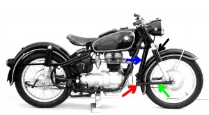
Leading arm suspension systems have been used in commercially produced motorcycles (eg the Earles forks) utilised by BMW in the 1950s, and shown here.  Note that the springs/dampers do not locate the suspension in any way, instead, the leading arms (green arrow) are pivoted at the point shown by the red arrow. The “forks” are indicated by the blue arrow and the springs/dampers by the black arrow.

A leading arm design of this type has anti-dive under brakes built in; as the braked wheel tries to keep turning, it pushes up on the pivot point, so counteracting the weight transfer forwards. In fact, some Earles machines are known to rise at the front under brakes.

But how does this front suspension design allow a movement backwards when the wheel hits a bump? As shown in the BMW design, it doesn’t – or at least, not much.

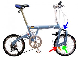
But as shown in the design of this bike, it does. Again the green arrow points to the leading arms, the red arrow to the pivot point, the blue arrow to the spring/damper and the black arrow to the forks. Note how the pivot point is low and so the wheel clearly moves backwards as it rises.

The bike is a Birdy folding machine and the front suspension travel is only about 15-20mm. I recently bought one and I am amazed at how well the front suspension works, especially given its minimal travel. It’s not effective over large bumps but it works brilliantly at removing vibration and harshness.

It’s also a particularly interesting design because in many suspension types, building-in anti-dive geometry actually causes the wheel to move forward as it moves upward, so making bump absorption worse rather than better. That’s not the case with this design.