Hybrid taxis

Posted on March 30th, 2014 in Hybrid Power,testing,Toyota by Julian Edgar

I recently spent some days in Darwin teaching people in government how to write clearly. It’s a long time since I’ve been in Darwin, and the growth and increasing affluence of the city was plain to see.

But the thing that fascinated me more than anything else in Darwin was the proliferation of Toyota hybrid taxis. The Prius, Prius V and Camry hybrid just dominate the taxi fleet.

Watching the few non-hybrid taxis sit there in ranks, waiting for customers with the car engines running to keep the air-conditioned cabins cool, it struck me how Toyota hybrids have a clear fuel economy advantage in these conditions.

And what’s that? Well, they can have the air con compressors and cabin fans operating with the engine switched off – until the HV battery gets low in charge, anyway.

One Prius taxi I went in had a dash displayed fuel economy of 7.5 litres/100km (horrendous for a Prius) but with the car being driven abysmally, and with all that time stopped with the air on, that was probably a pretty good figure compared with a conventional drivetrain.

(Yes the HV juice that runs the air con still needs to come from the petrol, but an engine is less efficient at idle than when driving the car, so overall, the fuel economy would benefit with the hybrid approach. Not to mention the battery juice achieved through braking regen.)

When I was in Germany a few months ago, there were many Prius taxis in the ranks – oftentimes, as many of the hybrid Toyotas as there were Mercedes and Volkswagens. I don’t think that fuel economy in those cool German cities would be a stellar advantage to the hybrids over diesels, so that brings up another taxi advantage. The Prius driveline is basically bulletproof – the engine, power split converter and electronics give extraordinarily little trouble. (That’s not just lucky – Toyota went to enormous pains to ensure that hybrids wouldn’t get a bad reputation through poor reliability.)

Taxi operators are among the hardest economic heads operating vehicles – they will use a car only if there is an overall economic benefit. So compared with other manufacturers, the taxi purchase / maintenance cost equation must be highly competitive for the Prius.

Wouldn’t it be funny if one of the greatest advances in car technology in the last 80 years – hybrids – ended up entering the mainstream through the back door of taxi use?

Another incredibly cheap digital meter

Posted on December 13th, 2011 in Driving Emotion,testing,tools by Julian Edgar

The story that we ran on the very low cost digital temperature display has proved to be extremely popular – hardly surprising, when only a few years ago such a display would have cost well over AUD$100. It is well made, has excellent functionality, and at a cost delivered to your house of about $25, absolutely unbeatable value.

But there’s also another digital display available at an unprecedented price. It’s not of direct relevance to cars or car modification, but if you’re interested in technical stuff, it’s a very good buy.

So what is it?

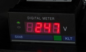
It’s a mains-powered LED panel meter that displays mains voltage. In other words, it constantly reads out the supply voltage to your house.

If you live in an area where you can see your (filament) lights dimming and brightening as loads are switched on and off inside the house, or switched on and off by neighbours, there are probably substantial variations from the nominal supply voltage.

Here in Australia the standard supply voltage is 230V with a plus tolerance of 10 per cent and a minus tolerance of 6 per cent – so from 216 – 253V. (Yes, isn’t that a huge range!)

At my house, in rural New South Wales, the monitored supply voltage has always stayed within those guidelines – but it has certainly used up a lot of that range!

The meter shows the turning on and off of an electric jug (the resulting voltage drop is about 2V) and clearly shows when the electric water heater cuts in and out. You can also see in winter when people in the hamlet are cranking-up the heaters, and in summer when they’re turning on the air-conditioners.

Cost of the meter? Just AUD$19 delivered to your door. Do an eBay search to find it and similar meters.

  • » Comments Comments Off on Another incredibly cheap digital meter

An unexpected modification outcome…

Posted on January 25th, 2011 in Aerodynamics,Driving Emotion,testing by Julian Edgar

One of the most exciting aspects about making car modifications is hitting the road and finding out how the car drives after the performance mods have been made. Recently, after fitting new intercooler plumbing, I did just this – but something rather unexpected happened.

But back a few steps.

I’d installed a new intercooler and built its associated pipework but I’d been a bit unhappy with the plumbing: it was about 80 per cent right but I thought I could do better the second time around. I wanted to change aspects like the tightness and number of bends, and to add some brackets to hold the pipes more securely in place. I also decided that this time I wouldn’t grind back any welds, thus leaving the joins much stronger.

So I measured and cut and welded and painted. The end result was one I was much happier with – I reckoned the revised plumbing fitted better, flowed more freely and would be more durable.

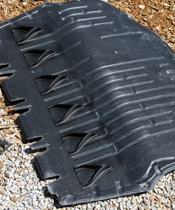
Fitting the plumbing required removing the bumper cover and undertray – a fiddly job. So while the undertray was removed, I decided to add some aero enhancements. Across the full width of the undertray I glued a line of Airtab vortex generators (pictured above). The idea was to encourage the boundary layer to stay attached to the undertray, so better drawing-out air from the engine bay as the flow moved past the end of the tray.

I already had the Airtabs and gluing them in place was only a five minute job – so if they worked, great; and if they didn’t, not much time or money lost.

But when I drove down the road for the first time the Airtabs were furthest from my mind. Because what I could feel was a vibration – a vibration through the floor, gear lever and steering wheel.

Being an older design diesel, the engine in my Skoda Roomster is quite coarse, and so my first thought was that the intercooler plumbing was too firmly mounted, so transferring engine vibration to the bodywork. This idea was a real downer: to access the brackets holding the plumbing would require taking off the undertray and front bumper cover – as I have said, a fiddly exercise. (And I hate doing those sorts of tasks!)

I checked under the bonnet to ensure that the pipework wasn’t banging against anything – but it looked fine. I idled the engine and physically felt the pipes – and yes, there was quite a lot of vibration occurring in them (perhaps also because of internal pressure waves – diesels breathe a lot of air, even at idle). But then again, that’d been the case with the first lot of plumbing – where driving vibration wasn’t an issue.

I went for a longer drive at highway speeds and the vibration was so bad that I knew something had to be done. And it was more than vibration – the car was also noisier. This was terrible – even in standard form the Roomster diesel is no paragon of NVH… and I’d made it a lot worse.

So how much of the noise and vibration was coming from the engine? I drove along at 100 km/h and then selected neutral, letting the revs drop back to idle. And you know what? – most of the vibration and noise remained!

So what the hell was going on?

Then I remembered the vortex generators. Surely, surely they couldn’t be causing these problems? There was only one way to find out – off they came.

Incredibly, the noise and vibration disappeared.

So the vortex generators must have been causing massive turbulence under the car – the vortices perhaps impinging on the floor near the firewall, shaking the car and generating noise. It seems implausible, but there’s no other possible explanation…

Designing a unique vehicle

Posted on February 4th, 2010 in Aerodynamics,automotive history,Materials,Safety,Suspension,testing by Julian Edgar

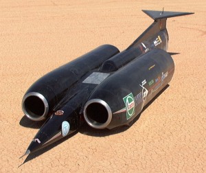
Recently I read Thrust, the book by Richard Noble on his life in breaking land speed records, culminating in the development of the ThrustSSC car – the current world land speed record holder. The record was achieved in 1997.

thrust ssc


The book is outstanding on a number of levels, including its honesty and clarity. The section where driver Any Green describes his techniques for steering the car is just amazing, as is the constant battle for funds that occurred every day of the project.

But one small part of the book particularly interested me: the section where the primary designer Ron Ayers describes how he went about designing the car.

The text is reproduced here:

How do you start designing a vehicle that is totally unique? Here are the characteristics of the problem that faced us:

1. By travelling supersonically on land we would be exploring a region where no-one had ventured, where even the problems could only be guessed at, so there were no known solutions.

2. As the aerodynamic forces involved were so enormous, any accident was likely to be fatal.

3. The project would always be underfunded, short of people and time.

4. There would be only one chance. The final car was also the first prototype. The first lines drawn on paper could well be the ones that are made. The very first assumptions and decisions, if incorrect, could put the project on the wrong track and there would be no chance of starting again.

Problem: how do you make those crucial first decisions when so much is uncertain?

First, every decision had to be a robust one. That meant it couldn’t be invalidated by subsequent decisions.

Second, we could only use technology we were very confident with. This militated against using the very latest technology in some cases.

Third, although direct experience of supersonic travel on land did not exist, we consulted widely, with aviation and automobile experts in industry, universities and research establishments. Experience with Thrust2 was invaluable, particularly in pinpoint¬ing practical and environmental problems that might otherwise be overlooked.

Fourth, where possible we left room for adjust¬ment or change, so we could incorporate knowledge acquired subsequently. Nothing was “hard wired”. One reason for using a steel chassis was that it could be modified if necessary.

Fifth, we didn’t try too hard to integrate the systems. If we needed to change one of them, we didn’t want to be forced to change them all.

Sixth, our choice of a twin-engined car made the design massively overpowered. Thus weight was not a critical factor.

The design resulting from such an approach must necessarily be “sub-optimum”. A second attempt, incorporating the lessons learned, would undoubtedly be better. But the design was proved in practice, and there was little about the basic concept that would need to be changed.

The more you read those notes, the more you realise the clarity of thought being employed: it’s also food for thought for anyone building a unique design of anything.

Noble and Green are currently involved with another land speed record car bid – the Bloodhound SSC.

Finding Suspension Roll and Pitch Centres

Posted on January 21st, 2010 in Opinion,pedal power,Suspension,testing by Julian Edgar

The trouble with suspension roll centres is that they’re often rather obscure in concept, let alone in location.

In this article I tried to simplify the concept of roll centres, largely by using geometric drawings.

(So what actually is a roll centre? It’s the imaginary point about which the car rolls. The front and rear suspension roll centres can be at different heights above the ground [but always on the centreline of the car] and on different vehicles the heights can vary from being above the ground, to at ground level, to below the ground.)

Normally roll centres are located by careful drawings of the suspension, a prerequisite being that you need to know the exact location of suspension pivot points, lengths of suspension arms and so on.

roll centre

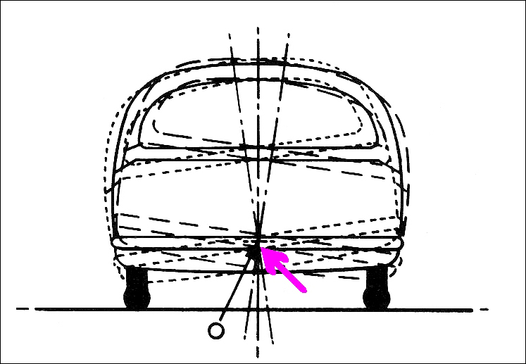
However, as shown in this diagram, the roll centre of an existing vehicle can be located by directly measuring the way the car behaves. If the car is physically rolled from side to side, there will be one point that never moves (or moves only minimally). That’s the roll centre. If multiple photos are taken of the car in end-view, this point can be easily located. 

This is a very useful technique – you can locate the roll centres for either the front or rear suspension, and no difficult measurements of the suspension geometry need be made.

And it’s not just the roll centre(s) that can be located in this way. In addition to roll, cars pitch – that is, the front dives and the rear rises, or vice versa. This occurs not only under acceleration and braking, but also over bumps in the road. The amount of pitch – or, more precisely, the pitch accelerations – are a major determinant of ride quality.

So how do you find the pitch centre? A book I have – Fundamentals of Vehicle Dynamics by Thomas Gillespie – devotes a number of pages of mathematics to locating the pitch centre of a car. However, as with the roll centre, pitch centres can be found by direct measurement.

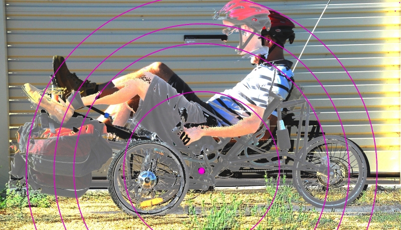
I did this the other day for my recumbent, pedal, suspension trike. I am doing a lot of work on its suspension, including measuring real-time pitch accelerations over bumpy surfaces. After making a host of measurements of these accelerations, I thought I should find where the pitch centre actually is.

I had two photos taken of the trike (with me on it), both in side view. In one pic, the front suspension was at max extension and the rear in max compression. In the other pic, the suspension extensions were the other way around. (I use air suspension and for this test I interconnected the units front to back, so giving zero resistance to pitch. To get the front to adopt max compression, I added some weights.)

I then overlaid the pics, playing with the image until I could find a point around which the trike body was rotating in pitch. This was best shown by placing radii centred on that point – the circular lines intersect with the same part of the trike in both pitch extremes. (It’s harder to explain than it is to do!)

trike pitch centre

In this pic, the pink dot is the pitch centre. As can be seen, the greatest mass on the machine (that’s me) is located above the pitch centre. Furthermore, a lot of that mass is located a fair way from the pitch centre, increasing the pitch moment of inertia. This is one reason that over rough ground, the pitch accelerations of the machine are very low.

Talking about moments of inertia in pitch is taking it a further step in complexity. But back to ‘centres’ –  if you’re grappling with the suspension design of a custom vehicle, it make things a lot clearer when you can so easily locate not only the roll centres, but also the pitch centre.

  • » Comments Comments Off on Finding Suspension Roll and Pitch Centres

DIY Breakthrough – FuelSmart

Posted on August 18th, 2009 in Economy,testing by Julian Edgar

Improving the fuel economy of vehicles is vastly harder than making them able to go faster: one is simply about jamming-in more fuel (and air) and the other, well, the other is about burning that fuel more efficiently.

That’s why I am so pleased with FuelSmart, the DIY electronic module that we’re covering in AutoSpeed this week and next.

Rather than modify the car’s engine management (or any other system), FuelSmart uses a dashboard LED to show when the car is being driven in a way that is not fuel-efficient. To put it simply: the indication tells you when you’re being a bad driver.

Having now driven many kilometres in my car equipped with FuelSmart, I realise that the action of the LED is training me to adopt a new driving style, one that is demonstrably more economical. It doesn’t mean that I am driving more slowly, it doesn’t mean that I act like there’s an egg between my foot and the throttle, and nor does it mean that the car is being mistreated.

Instead, I use plenty of throttle but get up through the gears fast, I lift right off when approaching traffic lights and other stopping points (rather than leisurely trail-throttle), and in slow-moving traffic I am one gear higher than I previously drove.

The sensitivity of FuelSmart is adjustable: you can set it so that it illuminates the LED only when you’re driving really badly, or at the other extreme, you can set it so that it indicates when you’re driving only a little badly.

During development I tried setting FuelSmart so that it was very sensitive and then went testing in heavy urban traffic. As always, the goal was to keep the warning LED off as much as possible.

And you know what?

After about 30 kilometres of driving, I was exhausted. It was just such hard work keeping the engine absolutely always in its optimal range of throttle position and rpm. The fuel economy was stunning, but hell, was I ever worn out!

Having experienced that extreme, I now run with the FuelSmart adjustment set much more modestly.

With it set in this way, I asked my wife to drive the car to the local shops. “Just drive to keep that new LED switched off as much as possible,” I said.

When she returned, I asked her what she thought.

“Well,” she said, “I’ll take your word for it that it improves fuel economy – it sure doesn’t feel that way! It’s telling me I’m not using enough throttle here, to lift right off there, to change up a gear here – it’s nothing like I expected it to be.”

Yes, I am very pleased with it – FuelSmart is a fascinatingly effective device.

Are all deflections bad?

Posted on May 5th, 2009 in electric,pedal power,Suspension,testing by Julian Edgar

One of the automotive ideas that seems to be taken as gospel is that the chassis and suspension arms should be stiff – that is, neither should deflect when subject to load. In fact, if I’d had a dollar for every time I’ve read that ‘good handling depends on a stiff chassis’ I’d be richer than I am.

But I think that, especially for ultra-light vehicles, this notion is simplistic.

Firstly, every structure deflects under load. That deflection may be small, but it occurs. Even the Sydney Harbour Bridge has an allowable deflection under maximum load of 4.5 inches (114mm) in the centre of its span.

Secondly – and more importantly – chasing reduced deflection will add substantially to weight. The corollary of that – the lightest possible vehicle will always have deflections.

Finally, not all deflections are bad.

Let’s start off with the last. Most cars use rubber bushes that are designed to have differing stiffnesses in differing planes. One reason for this is so that wheels can move fractionally backwards when they meet a bump, reducing harshness. Another reason is that in some (many?) suspensions, if the bushes didn’t have ‘give’, the suspension would lock up solid during travel.

Passive steering suspension systems – the first well publicised was the Porsche ‘Weissach’ axle of the 928 – often use bushes that deflect, or links that give an effectively ‘non-stiff’ suspension in some planes.

Going backwards to the second point, getting rid of measurable deflections in chassis and suspension arms will result in a major increase in weight. In ultra-light vehicles (eg those powered by human legs, a small petrol motor or an electric motor), and especially those made from chrome moly steel tube, deflections under major loadings are often able to be seen by eye.

For example, the peripheral torsional wind-up of a front suspension arm might be 5mm or more under maximum braking, and under max cornering there might be 3 or 4mm of bending in wheel supports. In a human powered vehicle (HPV) with a recumbent seat and front pedals, boom flex under maximum pedalling force can often be 10mm or more.

So does all this matter? In some cases (like boom flex, that subtracts from the power available from the rider), yes it does.

But in other cases – not necessarily.

What is required is that the structure is never stressed to the point of failure, and that the vehicle dynamics remain consistent.

I have been musing over these ideas in the context of the HPV I have been building.

I know that under brakes the beam front axle will torsionally wind-up, reducing the static castor of the front, steering wheels. That might lead to steering dartiness under brakes – but for the fact that when the front brakes are in action, the vehicle has some dive, that in turn causes a rapid increase in castor.

On my previous recumbent trike design (called the Air 150), I had difficulties in getting rid of steering twitchiness. The problem felt all the world like toe-in bump steer, where I’d put on some steering lock, the machine would roll slightly – and the outer wheel would toe-in, giving a sharper steering response than requested. That was the theory – but I found this odd when on the workshop floor, toe-in on bump was small or non-existent.

But I now wonder if the outer semi-leading suspension arm wasn’t flexing sideways a little with the sudden application of the lateral force, which in turn caused “turn-in steer” as the suspension arm and the steering tie-rod flexed through different arcs.

Certainly, at the very early stage of testing I am at with my current HPV ‘Chalky’, there’s no steering twitchiness on turn-in – and the front suspension is laterally much stiffer than the previous design.

(I fixed the Air 150’s twitchiness by setting the suspension up with either static toe-out, or toe-out on bump – but the problem returned when carrying really big loads. If the arms were bending laterally, perhaps it just needed even more static or bump toe-out to compensate?)

And I guess that’s the point. In a vehicle – any vehicle – there will be dynamic variations that don’t match the static settings.

(Many years ago, I remember having a wheel alignment done on my Daihatsu Mira Turbo. I was happy with the alignment machine’s read-outs – but then the mechanic got me to sit in the driver’s seat. On that simple car, the suspension settings immediately changed!)

If the weight of the vehicle has been has to be kept to an absolute minimum, and so major deflections occur in the suspension and frame, the trick is to optimise the direction of those deflections so that they don’t subtract from – and possibly even add to – the on-road experience.

That’s a very different notion to ‘keep everything as stiff as possible’.

When wheels steer themselves

Posted on April 2nd, 2009 in Driving Emotion,Handling,Suspension,testing by Julian Edgar

I thought that the idea that car wheels just went up and down over bumps, and were steered only when the driver turned the steering wheel, was pretty passé.

Passive ‘steer’ systems have been in production cars for many years, normally of the rear end.

In broad brush strokes, the systems work like this: The rear bushes are set with differing stiffnesses in different planes, such that when the wheel is subjected to a lateral force (as it is in cornering), it no longer remains parallel with the car’s long axis – that is, it steers.

For example, rear wheel compliance steer is often set to give toe-in, thus settling the cornering car.

The original Mazda MX5 / Miata had such a system. (It’s worth pointing out that the MX5 is generally regarded as one of the best handling, relatively cheap, cars ever released.) In their 1989 book MX-5 – the rebirth of the sports car in the new Mazda MX5, Jack Yamaguchi and Jonathon Thompson write:

No Mazda rear suspension is complete without some form of self-correcting geometry, as have been seen in the fwd 323 and 626’s TTL (Twin Trapezoidal Links), the 929’s E-links and the RX-7’s complex DTSS. The MX-5 double wishbones are no exception, though to a lesser degree. The designers need not worry about camber changes; a recognized virtue of the unequal length A-arm suspension is the admirable ability to maintain the tires’ contact area true to the road surface, attaining a near-zero camber change.

So the chassis designers’ efforts were directed at obtaining a desired amount of toe-in attitude that improves vehicle stability in such maneuvers as spirited cornering and rapid lane changes. Toe-in was to be introduced when the suspension is subjected to lateral force, not to accelerative or braking force. They considered that the MX-5 with its configuration, weight and suspension, would have sound basic handling characteristics, and the lateral reaction would be all it would require to further enhance its vehicle dynamics.

The lower H arm’s wheel-side pivots, which carry the suspension upright, have rubber bushings of different elasticity rates. The rear pivot is on a firmer rubber bushing than the front. The front rubber bushing deforms more under load induced by lateral force, and introduces an appropriate amount of wheel toe-in, which is in the final production tune a fraction of a degree.

Pretty well all current front-wheel drive cars have some form of passive rear wheel steering. The Honda Jazz uses a tricky torsion beam rear axle in which, according to Honda, “the amount of roll steer and roll camber has been optimised to deliver steady handling”.
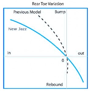
But even better, the company has released graphs showing the toe variation over suspension travel (note: travel, rather than lateral force), with the current model compared with the previous design. As can be clearly seen, in bump (as would occur to the outer wheel when cornering) the Jazz (especially the new model) has an increasing amount of toe-in. Also note the differing shape of the curves in rebound (droop).

And it’s not just the ostensibly non-steered end that uses toe variations built into the suspension design.

Several suspension textbooks that I have suggest that setting up the front, steering wheels for non-zero bump steer can be advantageous. Chassis Engineering by Herb Adams (incidentally, a very simple book much under-rated) states:

Exactly how much bump steer you need on your car is like most suspension settings—a compromise. It is common to set the bump steer so that the front wheels toe-out on a bump. This will make the car feel more stable, because the car will not turn any more than the driver asks.

To understand this effect, picture what would happen if your car had toe-in on bump. As the driver would start a turn, he would feed in a certain amount of steering angle. As the car built up g-forces, the chassis would roll and the outside suspension would compress in the bump direction. If the car had toe-in on bump, the front wheels would start to turn more than the driver asked and his turn radius would get tighter. This would require the driver to make a correction and upset the car’s smooth approach into the turn. The outside tire is considered in this analysis because it carries most of the weight in a turn.

Assuming that your car has the bump steer set so that there is toe-out in the bump direction, the next consideration is how much toe-out. If the car has too much toe-out in bump, the steering can become imprecise, because the suspension will tend to negate what the driver is doing with the steering wheel. Also, if there is too much bump steer, the car will dart around going down the straightaway. A reasonable amount of bump steer would be in the range of .010 to .020 per inch of suspension travel.

Fundamentals of Vehicle Dynamics by Thomas D Gillespie positively describes using roll steer, where the toe variation of the left-hand and right-hand wheel is in the same direction, to alter understeer and oversteer effects.

Even that most exotic of road cars, the McLaren F1, had designed-in passive steer.

Writing in an engineering paper released in 1993, SJ Randle wrote of the front suspension: “Lateral force steer…. was 0.15 degrees/g toe out under a load pushing the contact patch in towards the vehicle centreline. This is a mild understeer characteristic – precisely what we wanted.”

In the case of the rear suspension, “the net result being a mild oversteer characteristic (ie toe out under a force towards the car’s centreline) or around 0.2 degrees/g. We had hoped for an understeer of 0.1 degrees/g.”

Such passive steer suspension behaviour would become especially important in vehicles that, in order to achieve other design aims, have dynamic deficiencies. So for example, a very light car that is aerodynamically neutral in lift, and has a low aero drag, is likely to be susceptible to cross-winds. On bump the passive toe-in of the rear wheels, and toe-out of the front wheels, would help correct this yaw.

Note that adopting these techniques doesn’t require the actual mechanical complexity – or weight – of the suspension systems to change.

But of course it’s quite possible to over-do these effects. As indicated in the quotes above, we’re talking very small steer angle changes. You can’t even transfer the ideas from car to car: the current Honda Jazz steers fine; the Honda City (that apparently uses the Jazz rear suspension) has an unmistakeable, unhappy, ‘rear steer’ feel that is disconcerting on quick lane changes. 

But it seems to me that if you are building any bespoke vehicle and simply state point-blank that there should be no bump steer at the front, and no lateral compliance leading to toe changes at the back, you’re taking away a pretty important string from your bow.

The Best DIY Tools and Techniques

Posted on March 31st, 2009 in diesel,Driving Emotion,Economy,Mufflers,Opinion,pedal power,testing by Julian Edgar

This week in AutoSpeed we start a new series that I’ve immodestly called the ‘Ultimate DIY Automotive Modification Kit’.

It’s not the sort of material that you’d find anywhere else but at AutoSpeed – and, perhaps for that reason, longstanding readers will have seen much of the content before.

What the series does is integrate the testing and modification techniques that over the years I’ve discovered  to work for all cars.

Yes, all cars.

Use a variety of approaches in suspension design

Posted on March 5th, 2009 in Suspension,testing,tools by Julian Edgar

Suspension design is great fun, and very challenging.

I am not talking about ‘design’ as in picking which upgrade kit to buy for your car, but much more fundamental aspects like developing a whole new suspension – anti-dive percentage, camber change, longitudinal and lateral virtual swing arm lengths… stuff like that.

I haven’t done it for a car but I have applied exactly the same concepts to human powered vehicles.

When I designed the double wishbone front end for my first recumbent trike, I struggled with setting the ground rules. Like the:

• Position of front upper wishbone mount
• Position of rear upper wishbone mount
• Position of front lower wishbone mount
• Position of rear lower wishbone mount
• Position of upper ball-joint
• Position of lower ball-joint

With each location defined in three planes, that’s 18 variables. Add to that wheel offset and diameter, and inner and outer steering tie rod positions, and you’re looking at 26 or more accurate dimensions needed before you can even start.