Welcome to the Autospeed Blog. Use of this site must adhere to our terms and conditions.

Designing a unique vehicle

Posted on February 4th, 2010 in Aerodynamics,automotive history,Materials,Safety,Suspension,testing by Julian Edgar

Recently I read Thrust, the book by Richard Noble on his life in breaking land speed records, culminating in the development of the ThrustSSC car – the current world land speed record holder. The record was achieved in 1997.

thrust ssc


The book is outstanding on a number of levels, including its honesty and clarity. The section where driver Any Green describes his techniques for steering the car is just amazing, as is the constant battle for funds that occurred every day of the project.

But one small part of the book particularly interested me: the section where the primary designer Ron Ayers describes how he went about designing the car.

The text is reproduced here:

How do you start designing a vehicle that is totally unique? Here are the characteristics of the problem that faced us:

1. By travelling supersonically on land we would be exploring a region where no-one had ventured, where even the problems could only be guessed at, so there were no known solutions.

2. As the aerodynamic forces involved were so enormous, any accident was likely to be fatal.

3. The project would always be underfunded, short of people and time.

4. There would be only one chance. The final car was also the first prototype. The first lines drawn on paper could well be the ones that are made. The very first assumptions and decisions, if incorrect, could put the project on the wrong track and there would be no chance of starting again.

Problem: how do you make those crucial first decisions when so much is uncertain?

First, every decision had to be a robust one. That meant it couldn’t be invalidated by subsequent decisions.

Second, we could only use technology we were very confident with. This militated against using the very latest technology in some cases.

Third, although direct experience of supersonic travel on land did not exist, we consulted widely, with aviation and automobile experts in industry, universities and research establishments. Experience with Thrust2 was invaluable, particularly in pinpoint¬ing practical and environmental problems that might otherwise be overlooked.

Fourth, where possible we left room for adjust¬ment or change, so we could incorporate knowledge acquired subsequently. Nothing was “hard wired”. One reason for using a steel chassis was that it could be modified if necessary.

Fifth, we didn’t try too hard to integrate the systems. If we needed to change one of them, we didn’t want to be forced to change them all.

Sixth, our choice of a twin-engined car made the design massively overpowered. Thus weight was not a critical factor.

The design resulting from such an approach must necessarily be “sub-optimum”. A second attempt, incorporating the lessons learned, would undoubtedly be better. But the design was proved in practice, and there was little about the basic concept that would need to be changed.

The more you read those notes, the more you realise the clarity of thought being employed: it’s also food for thought for anyone building a unique design of anything.

Noble and Green are currently involved with another land speed record car bid – the Bloodhound SSC.

Finding Suspension Roll and Pitch Centres

Posted on January 21st, 2010 in Opinion,pedal power,Suspension,testing by Julian Edgar

The trouble with suspension roll centres is that they’re often rather obscure in concept, let alone in location.

In this article I tried to simplify the concept of roll centres, largely by using geometric drawings.

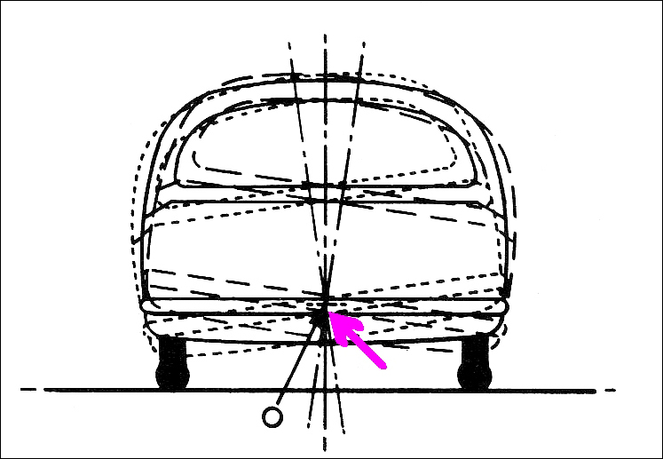
(So what actually is a roll centre? It’s the imaginary point about which the car rolls. The front and rear suspension roll centres can be at different heights above the ground [but always on the centreline of the car] and on different vehicles the heights can vary from being above the ground, to at ground level, to below the ground.)

Normally roll centres are located by careful drawings of the suspension, a prerequisite being that you need to know the exact location of suspension pivot points, lengths of suspension arms and so on.
roll centre

However, as shown in this diagram, the roll centre of an existing vehicle can be located by directly measuring the way the car behaves. If the car is physically rolled from side to side, there will be one point that never moves (or moves only minimally). That’s the roll centre. If multiple photos are taken of the car in end-view, this point can be easily located. 

This is a very useful technique – you can locate the roll centres for either the front or rear suspension, and no difficult measurements of the suspension geometry need be made.

And it’s not just the roll centre(s) that can be located in this way. In addition to roll, cars pitch – that is, the front dives and the rear rises, or vice versa. This occurs not only under acceleration and braking, but also over bumps in the road. The amount of pitch – or, more precisely, the pitch accelerations – are a major determinant of ride quality.

So how do you find the pitch centre? A book I have – Fundamentals of Vehicle Dynamics by Thomas Gillespie – devotes a number of pages of mathematics to locating the pitch centre of a car. However, as with the roll centre, pitch centres can be found by direct measurement.

I did this the other day for my recumbent, pedal, suspension trike. I am doing a lot of work on its suspension, including measuring real-time pitch accelerations over bumpy surfaces. After making a host of measurements of these accelerations, I thought I should find where the pitch centre actually is.

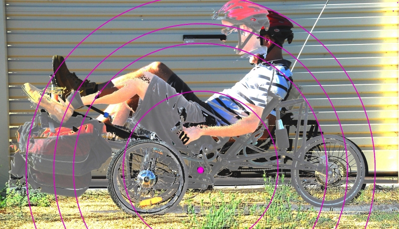
I had two photos taken of the trike (with me on it), both in side view. In one pic, the front suspension was at max extension and the rear in max compression. In the other pic, the suspension extensions were the other way around. (I use air suspension and for this test I interconnected the units front to back, so giving zero resistance to pitch. To get the front to adopt max compression, I added some weights.)

I then overlaid the pics, playing with the image until I could find a point around which the trike body was rotating in pitch. This was best shown by placing radii centred on that point – the circular lines intersect with the same part of the trike in both pitch extremes. (It’s harder to explain than it is to do!)
trike pitch centre

In this pic, the pink dot is the pitch centre. As can be seen, the greatest mass on the machine (that’s me) is located above the pitch centre. Furthermore, a lot of that mass is located a fair way from the pitch centre, increasing the pitch moment of inertia. This is one reason that over rough ground, the pitch accelerations of the machine are very low.

Talking about moments of inertia in pitch is taking it a further step in complexity. But back to ‘centres’ –  if you’re grappling with the suspension design of a custom vehicle, it make things a lot clearer when you can so easily locate not only the roll centres, but also the pitch centre.

  • » Comments Comments Off on Finding Suspension Roll and Pitch Centres

Putting the Power of Electronics in Your Hands

Posted on October 6th, 2009 in Opinion by Julian Edgar

I’ve been writing about electronics for nearly as long as I have been writing about cars. And, before I wrote about the subject, I played with wiring and batteries and lights and components.

But to be honest, I have always found electronics an immensely frustrating hobby. Working with integrated circuits and resistors and capacitors, more often than not I’d end up with a project that didn’t work. I’d solder a pin wrongly on the IC, or get a capacitor in the circuit the wrong way around, or do something or other – oftentimes, I didn’t even know what I’d done wrong… but the circuit didn’t work. And once a circuit doesn’t work, faultfinding it is very difficult indeed.

And even when building kits, I reckon that about one-third of the time I put them together wrongly – and so the result was the same. Many of the kits didn’t work.

(Incidentally, my wife Georgina is vastly better at building electronic kits than I am, but she also has a lot less electronics knowledge. The moral of that story is that care, patience, a good eye and a steady hand are more important to kit success than knowledge…)

At one stage when I contributed to an electronics magazine, they chose to put at my disposal a gifted and experienced electronics engineer. I sure enjoyed electronics then! I could just come up with the ideas and he made it happen – even to the extent of building the prototype kits.

But even in that situation there was a problem: once the project had been signed off and the kit published in the magazine (and available in shops), it was too late to make any changes. I didn’t have the knowledge to make hardware changes, and with the software written in obscure code, I’d no hope in that area.

But – sound the trumpets! – now things have completely changed.
 
As I write this, I’ve just spent the last two days working with a brand new electronics system. I haven’t had to pick up a soldering iron, I’ve built something like a dozen projects, and I’ve been able to make all sorts of subtle changes to the way in which the projects work. And, when I’ve made a mistake, I’ve been able to fix it with ease.

It sounds too good to be true, so how can it work?

The approach is called the EZ System and it’s been developed by Australian company eLabtronics.

First up, eLabtronics has developed (and is further developing) a range of programmable universal control modules. Incorporating a microcontroller (a brain) and a variety of other components, it’s the prebuilt starting point for a huge range of projects.  The modules come with screw type connectors, making wiring easy and safe.

Also available are pre-wired components – LEDs, temperature sensors, light sensors, pots and pushbuttons. All the components use the same wiring colour code and come with any required additional components already in their looms. So for example, you don’t need to worry about dropping resistors on LEDs – you just connect the LED’s pre-formed wiring straight to the module.

But how does the module know what to do? The answer is the custom software you’ve programmed into it – and what an answer it is!

The radical breakthrough in the eLabtronics ezSystem is the ezCoreChart software. If you can draw a flow-chart on a piece of paper, you can program the electronic module with this incredibly simple and versatile approach.

Let’s say you want to monitor a temperature and turn on an alarm buzzer when the temp reaches a certain point. If you were drawing a flow diagram, you might write one box that says ‘monitor temp’, another box that says ‘compare this temp to the set value’ and a third box that says ‘if temp is above the set value, switch on the buzzer’.

Well, that’s almost all you have to do in ezCoreChart! Just by clicking and dragging in some programming boxes, you can have fully functioning software for a temp alarm put together in literally minutes.

There’s no understanding needed of computer code, no building of electronics, no complicated soldering. Another software package – ezCircuit Designer – even shows you which connectors to wire the components to!

And there’s no frustration, no time wasted, no wrestling with stuff impossible to understand.

The electronic module can be programmed and re-programmed, so you can make as many changes to the system as you want. You decide the logic (or modify supplied programs) so you can get the exact outcome you want. The project can be as simple as the aforesaid temp alarm – or as complex as an intercooler water spray controller that monitors ambient temp, intercooler temp and throttle position! All for the same price!

Whether you’re a car modifier, hobbyist, teacher, modeller or engineer, eLabtronic’s ezSystem radically changes how you can make electronics work for you.

I can say with genuine belief that it is the most exciting development in DIY electronics I’ve ever seen – and this week, we start covering the system in AutoSpeed.

Footnote: while I have been deeply involved in the development of the eLabtronics EZ system, I have no financial interest in it.

DIY Breakthrough – FuelSmart

Posted on August 18th, 2009 in Economy,testing by Julian Edgar

Improving the fuel economy of vehicles is vastly harder than making them able to go faster: one is simply about jamming-in more fuel (and air) and the other, well, the other is about burning that fuel more efficiently.

That’s why I am so pleased with FuelSmart, the DIY electronic module that we’re covering in AutoSpeed this week and next.

Rather than modify the car’s engine management (or any other system), FuelSmart uses a dashboard LED to show when the car is being driven in a way that is not fuel-efficient. To put it simply: the indication tells you when you’re being a bad driver.

Having now driven many kilometres in my car equipped with FuelSmart, I realise that the action of the LED is training me to adopt a new driving style, one that is demonstrably more economical. It doesn’t mean that I am driving more slowly, it doesn’t mean that I act like there’s an egg between my foot and the throttle, and nor does it mean that the car is being mistreated.

Instead, I use plenty of throttle but get up through the gears fast, I lift right off when approaching traffic lights and other stopping points (rather than leisurely trail-throttle), and in slow-moving traffic I am one gear higher than I previously drove.

The sensitivity of FuelSmart is adjustable: you can set it so that it illuminates the LED only when you’re driving really badly, or at the other extreme, you can set it so that it indicates when you’re driving only a little badly.

During development I tried setting FuelSmart so that it was very sensitive and then went testing in heavy urban traffic. As always, the goal was to keep the warning LED off as much as possible.

And you know what?

After about 30 kilometres of driving, I was exhausted. It was just such hard work keeping the engine absolutely always in its optimal range of throttle position and rpm. The fuel economy was stunning, but hell, was I ever worn out!

Having experienced that extreme, I now run with the FuelSmart adjustment set much more modestly.

With it set in this way, I asked my wife to drive the car to the local shops. “Just drive to keep that new LED switched off as much as possible,” I said.

When she returned, I asked her what she thought.

“Well,” she said, “I’ll take your word for it that it improves fuel economy – it sure doesn’t feel that way! It’s telling me I’m not using enough throttle here, to lift right off there, to change up a gear here – it’s nothing like I expected it to be.”

Yes, I am very pleased with it – FuelSmart is a fascinatingly effective device.

Help design a car

Posted on July 27th, 2009 in Opinion by Julian Edgar

From Peter Pudney, supervisor of the development of Trev:

At some time during the past couple of years you have been one of the hundreds of people who has contacted me about Trev, the small green electric car designed and built at the University of South Australia (and as seen on TV, ABC Austraia’s The New Inventors). You probably
wanted:

A) to buy one
B) to build one
C) to help design the next version
D) to get more information
E) to go on a mailing list
F) some or all of the above, or something else entirely.

If it was A, I am afraid I still can’t help you. But for everyone else, I am pleased to announce:

 TREVipedia

I have been intending for some time to put together a web site that will help coordinate the efforts of people wanting to help develop Trev further. About a month ago I was contacted by Matt Green, who wanted to help (and to build a Trev). Matt has organised a web site and set up the wiki, and between us we have started writing TREVipedia. The aim of TREVipedia is to coordinate and document the development by enthusiasts of the next version of Trev. Ultimately, we hope the TREVipedia community will develop a certified “kit car” design with standard parts, and provide information that will help people build their own.

There is not much on TREVipedia yet. We have included some information about the UniSA prototype car, some of the lessons learned, some basic CAD models, and some ideas for future versions. I will continue to add information, but we need the community to contribute by asking questions, answering questions, contributing ideas, designing, and helping organise the community and the wiki.

Take a look at TREVipedia. If you are interested in contributing, create a login name for yourself and and start editing pages (there is an edit tab at the top of each page). If you have questions, ask them on one of the discussion pages. If you see an error on one of the pages, or have useful information to contribute, edit the page. Don’t forget to save your changes. If you make a mistake, it is easy to undo (or someone else will fix it).

Home Workshop Performance

Posted on May 14th, 2009 in Driving Emotion,Opinion,tools by Julian Edgar

Our ‘Building a Home Workshop’ series (starts here) has been very popular. So what’s the workshop like after being in use for 9 months? What’s been learned about its performance in that time?

Firstly, the excellent.

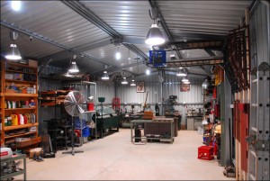
The lighting system (an expensive and very powerful system using a lot of suspended metal halide luminaries) is well worth the time and money involved in its installation. You can be working in the late afternoon and as evening falls, not even notice the change in lighting. You can work as efficiently in the middle of the night as the middle of the day.

The internal layout – the position of power points, machine tools and workbenches – has also proved excellent. The ‘island’ workbench is particularly effective, as is the proximity of the welding bench to the main workbench. 

The tall headroom is also noticeable every time I swing a piece of tube or even carry the ladder. Talking about the ladder, the storage of items high up (clearing floor space) has also proved to work very well.

Now, the bad.

I chose to install two skylight panels on the north-facing part of the roof, down the end of the workshop furthest from the roller doors. These work well in that the summer heat build-up caused by their presence is limited but they still provide a lot of light. However, I should have used one more panel so that the back wall of the workshop (where the machine tools are located) was evenly illuminated. As it is now, on a cloudy day, the drill press, grinder and hydraulic press are a bit dim.

Ventilation is also not sufficient. Even with the two roller doors up, the twin whirligig ventilators working and a fan moving air within the workshop, the build-up of fumes while brazing or welding is excessive. This is one aspect I think I will have to change – either adding an extraction hood and exhaust fan over the welding bench or placing an opening window in the far wall.

Finally, the concrete floor has proved to be very soft, not just in the second batch (which I always knew was soft) but also in the first batch. To avoid damaging the floor, items cannot be dragged across it and nothing can be hammered on it.

Overall? Very happy indeed.

An extraordinary man – and his car

Posted on May 12th, 2009 in automotive history,Opinion by Julian Edgar

I am not usually one to read business or financial thrillers; there’s too much I simply don’t understand. But Delorean, written by Ivan Fallon and James Strodes and published in 1983, is simply a helluva book.

The history of the Delorean DMC12 car is widely known – we’ve done a fairly typical story ourselves (see here) – but it’s the background financial and personal shenanigans that make for fascinating reading. 

The authors are ungenerous of John Z Delorean, but any feeling that they’re being mean just for sensationalism quickly goes out the window when we start learning about the financial approaches taken within the company.

The company – funded effectively by the British taxpayer – threw money around with an indefensible largesse, while Delorean himself appeared to have delusions of grandeur (the latter perhaps required of someone propping up a house of cards). 

Also rather interesting is the skeleton company set up to apparently channel tax-free money to Colin Chapman of Lotus (Lotus did most of the development work on the car) and to Delorean himself.

Used to dealing with ethical and sober companies, the British government – and its agencies – simply couldn’t believe what they were seeing happening to their money. But, caught in a political bind, they kept handing Delorean more and more!

The authors are financial experts – not automotive writers – and there a few automotive technology errors and shortcomings.  Tech detail on the development of the car itself is also only briefly covered (although even that coverage is often interesting).

But if you want to read a book that shows how one man can manipulate situations to his advantage – or, perhaps more generously, a book about the burning ambition of a man who would do anything to succeed – this is an amazing read.

The (lack of) pace in retail change

Posted on May 7th, 2009 in Opinion by Julian Edgar

The pace of change in the retailing of goods seems to me to be progressing awfully slowly.

Despite the massive impact of the web, and the much lower real costs of accessing information and shipping goods, many shops seem to be stuck in a time that I thought was long past.

Or, would be long past by now, anyway.

The other day my wife and I bought a tent. The tent needs to match very specific criteria. It needs to weigh under 5kg, be a ‘four season’ design, and have room for three people and their gear. It also needs lots of tie-downs. The tent will be used in cycle touring both in Australia and internationally.

Now there are a few things in this list that make sourcing such a tent difficult.

Firstly, most tents sold in Australia are two or three season tents – fair enough, given our relatively mild climate.

Secondly, in light-weight tents, the majority are tight two-person tents, or very tight three-person tents. (Or of course single person tents.)

Thirdly, there are few tents around the thousand dollar budget that we’ve found is needed to buy a quality tent of this type.

We’ve been looking and assessing tents for about a year. In that time, we’ve visited about fifteen different camping shops in three states. As expected, none of these shops had on display a tent matching these specs. All could get such a tent into stock, but didn’t have anything for us to look at.

What was completely unexpected, however, is the poor quality of advice we were constantly given. After stating the criteria and why we had devised such criteria, the camping shop staff invariably asked: “So, where are you going on your trip?” (as if we were buying a $1000 tent for a one-off trip!) and then proceeded to try to sell us an inferior tent that they just happened to have in stock.

After this happened about the tenth time, I got jack of it and decided the tent would need to be bought sight-unseen. I found a suitable tent, did substantial on-line research, and then sent out about 15 emails, one to each of the tent’s Australian retailers. In the email I simply asked for price and availability of the tent I had in mind.

The first surprise was how long some shops took to reply – in one case, over a week. The second surprise was that most shops just quoted the recommended retail price, and said they didn’t have any in stock but could get them. (Glad I didn’t bother visiting those shops, then.)

However, one dealer, at a relatively remote country location, came back with a good email. He could get the tent no problems, it said. The current model was $XXX (about 15 per cent under recommended retail), but he also had a previous model that broke down rather differently, adding potential versatility in the way it could be carried. Both tents could be sent free freight to wherever I was in Australia. Any questions or advice needed – please email or call.

I rang the next day and discussed in depth the purchase, the criteria, our potential use. The man knew the tent well – he hired them out. He also was an experienced touring cyclist, as well as being very familiar with snow country – the worse conditions for a tent.

We paid by direct bank transfer, got a quick email acknowledgement and a few days later had the tent – direct-shipped not from the shop but from the wholesaler.

I don’t know if where we bought our tent there is a bricks and mortar shop – or he works out of his bedroom. And why would I care? He had the best advice, best price, free freight and direct-shipped from the distributor, saving valuable time.

A retail shop where you can touch and feel the goods has obvious advantages. But the more specialised the goods, the less relevant a retail shop seems to be.

As I said at the beginning, you’d think that by now things would have changed far more than they evidently have…

Are all deflections bad?

Posted on May 5th, 2009 in electric,pedal power,Suspension,testing by Julian Edgar

One of the automotive ideas that seems to be taken as gospel is that the chassis and suspension arms should be stiff – that is, neither should deflect when subject to load. In fact, if I’d had a dollar for every time I’ve read that ‘good handling depends on a stiff chassis’ I’d be richer than I am.

But I think that, especially for ultra-light vehicles, this notion is simplistic.

Firstly, every structure deflects under load. That deflection may be small, but it occurs. Even the Sydney Harbour Bridge has an allowable deflection under maximum load of 4.5 inches (114mm) in the centre of its span.

Secondly – and more importantly – chasing reduced deflection will add substantially to weight. The corollary of that – the lightest possible vehicle will always have deflections.

Finally, not all deflections are bad.

Let’s start off with the last. Most cars use rubber bushes that are designed to have differing stiffnesses in differing planes. One reason for this is so that wheels can move fractionally backwards when they meet a bump, reducing harshness. Another reason is that in some (many?) suspensions, if the bushes didn’t have ‘give’, the suspension would lock up solid during travel.

Passive steering suspension systems – the first well publicised was the Porsche ‘Weissach’ axle of the 928 – often use bushes that deflect, or links that give an effectively ‘non-stiff’ suspension in some planes.

Going backwards to the second point, getting rid of measurable deflections in chassis and suspension arms will result in a major increase in weight. In ultra-light vehicles (eg those powered by human legs, a small petrol motor or an electric motor), and especially those made from chrome moly steel tube, deflections under major loadings are often able to be seen by eye.

For example, the peripheral torsional wind-up of a front suspension arm might be 5mm or more under maximum braking, and under max cornering there might be 3 or 4mm of bending in wheel supports. In a human powered vehicle (HPV) with a recumbent seat and front pedals, boom flex under maximum pedalling force can often be 10mm or more.

So does all this matter? In some cases (like boom flex, that subtracts from the power available from the rider), yes it does.

But in other cases – not necessarily.

What is required is that the structure is never stressed to the point of failure, and that the vehicle dynamics remain consistent.

I have been musing over these ideas in the context of the HPV I have been building.

I know that under brakes the beam front axle will torsionally wind-up, reducing the static castor of the front, steering wheels. That might lead to steering dartiness under brakes – but for the fact that when the front brakes are in action, the vehicle has some dive, that in turn causes a rapid increase in castor.

On my previous recumbent trike design (called the Air 150), I had difficulties in getting rid of steering twitchiness. The problem felt all the world like toe-in bump steer, where I’d put on some steering lock, the machine would roll slightly – and the outer wheel would toe-in, giving a sharper steering response than requested. That was the theory – but I found this odd when on the workshop floor, toe-in on bump was small or non-existent.

But I now wonder if the outer semi-leading suspension arm wasn’t flexing sideways a little with the sudden application of the lateral force, which in turn caused “turn-in steer” as the suspension arm and the steering tie-rod flexed through different arcs.

Certainly, at the very early stage of testing I am at with my current HPV ‘Chalky’, there’s no steering twitchiness on turn-in – and the front suspension is laterally much stiffer than the previous design.

(I fixed the Air 150’s twitchiness by setting the suspension up with either static toe-out, or toe-out on bump – but the problem returned when carrying really big loads. If the arms were bending laterally, perhaps it just needed even more static or bump toe-out to compensate?)

And I guess that’s the point. In a vehicle – any vehicle – there will be dynamic variations that don’t match the static settings.

(Many years ago, I remember having a wheel alignment done on my Daihatsu Mira Turbo. I was happy with the alignment machine’s read-outs – but then the mechanic got me to sit in the driver’s seat. On that simple car, the suspension settings immediately changed!)

If the weight of the vehicle has been has to be kept to an absolute minimum, and so major deflections occur in the suspension and frame, the trick is to optimise the direction of those deflections so that they don’t subtract from – and possibly even add to – the on-road experience.

That’s a very different notion to ‘keep everything as stiff as possible’.

Grossly misleading technical articles

Posted on April 30th, 2009 in AutoSpeed,Opinion by Julian Edgar

Long ago, even before I was a Geography teacher, I studied how to teach it. The head of the Geography department at college was a very smart person, and a brilliant teacher.

One day we were talking about teaching analogies and models, and the difficulty in simplification of knowledge without introducing straight-out erroneous ideas.

His example of the latter was: Clouds bumping into each other make thunder.

Much better, he pointed out, to say even to the youngest child: Thunder happens because of lightning.

In fact, clouds are a good example of these ideas. My little boy, who is 4 years old, asks what clouds are made of.

Tiny, tiny water droplets, I say.

So, how does rain happen, he asks?

I say: The tiny droplets run into each other and join together. When they are big enough, they fall to the ground.

While I am saying this, sometimes I think of a much more sophisticated model: water vapour, latent heat of evaporation and condensation, relative humidity, dew-point, hygroscopic nuclei – and other concepts.

A meteorologist would probably think of vapour pressure, a chemist might think at a molecular level, a physicist might consider terminal velocities, a climatologist might consider climate change, a minister of religion might think of God, an agnostic might think of the magnificence of nature.

In the description of clouds and rainfall that I say to my son, I am conscious of the gross simplifications I am making.

But that’s OK: every single thing I know about the world is a gross simplification of reality.

The intellectual models I use to make sense of what occurs around me are just reducible approximations of what really happens.

When I write technical articles in AutoSpeed, I am conscious that all the time I am presenting fundamentally simplistic models. I hope that they’re not of the ‘clouds bumping into each other make thunder’ type: but they may be.

Recently, I wrote an article on suspension roll centres, virtual pivot points and other ways of analysing suspension designs. In doing so, I consulted five different suspension design textbooks, and also considered very carefully the experience I have in developing human-powered vehicle suspensions, and modifying car suspensions.

As always, I was quite conscious during the writing of the article that the model I was presenting of reality was likely to be flawed: as I have already implied, every model we have of reality is, to a greater or lesser degree, flawed. However, I hoped that the information would benefit people’s understandings, especially in practical outcomes.

The day after finishing the article, I looked through a complex SAE paper on suspension roll centres. This paper immediately debunked several suspension ‘myths’, most of which I had implicitly or explicitly promulgated in the article I had written.

However, the paper was working at a level analogous to the ‘vapour pressure and hygroscopic nuclei’ theory of why rain falls: if I based my article on the SAE paper in question, perhaps less than half of one percent of AutoSpeed readers would understand anything I wrote. (If in fact I could understand it myself!)

So I could easily decide not to write anything at all: if it’s not ‘right’ and ‘correct’, surely it shouldn’t be written?

But that would be like saying to my son: I cannot tell you why rain falls; it’s too hard to understand.

I cannot tell you what a roll centre is; it’s too hard to understand.

Or I cannot tell you what a voltage is; it’s too hard to understand.

I cannot tell you what engine detonation is; it’s too hard to understand.

I cannot tell you how a tyre behaves when cornering, it’s too hard to understand.

And so on.

And these things – and all things – really are too hard to understand… if you want as ‘correct’ an understanding as it is currently possible to have.

Are my articles full of errors? So by definition, very likely.

Anyone who suggests that the technical articles they present for general readers are perfectly correct – or do not mislead in the slightest – just do not understand the nature of knowledge – and how all our descriptions of what goes on around us are just relatively simplistic models.

Me? I try to use the simplest model that’s consistent with not being grossly misleading…