 Julian Edgar, 50, has been writing about car modification and automotive technology for nearly 25 years. He has owned cars with two, three, four, five, six and eight cylinders; single turbo, twin turbo, supercharged, diesel and hybrid electric drivelines. He lists his transport interests as turbocharging, aerodynamics, suspension design and human-powered vehicles.

In-line shaft dyno

The other day I bought some manuals published in July 1960. They’re lecture notes from the Technical Training School for Qantas Empire Airways Ltd.
The notes are primarily on the Lockheed Electra, an aircraft powered by four Allison 501-D13 prop jet engines. These engines each developed about 4000hp.
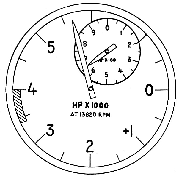
One of the very interesting technologies covered in the manuals is a real-time, on-board dyno. Yes, in the cockpit was a gauge that displayed the power being produced by the engine! This gauge was calibrated from minus 1000hp to plus 6000hp. Accuracy was quoted as being +/- 355hp.
So how was a real-time indication of power output gained?
On this turbo prop design – as with all turbo props that I’m aware of – a gearbox is used to reduce the speed of the turbine to that suitable for driving a propeller. The turbine is joined to the reduction gearbox by means of a driveshaft, splined each end. Surrounding this shaft is another shaft, this one splined only at the turbine end.
As the turbine drives the reduction gear box, the driveshaft torsionally twists. The greater the torque that is being transmitted, the greater the twist present in this shaft. But the other shaft, the one splined at just the turbine end, has no twist developed in it. Why not? Because it isn’t transmitting any torque.
Therefore, a comparison of the relative ‘angles of twist’ of the outer (“torquemeter”) shaft and the driveshaft indicates how much torque is being developed by the turbine. If the speed of shaft rotation is known, then the power can be readily calculated.
In the Electra system, angular displacement of the two shafts was measured by sensors watching 40 teeth machined on each shaft. The sensors worked with control electronics that detected the phase angle between the impulses picked up from the rotating teeth – rather like a crankshaft position sensor on a car, but comparing the angular displacement between two sets of teeth.

In those days, the electronics were not easily capable of also measuring speed and then doing the power calculation, so as shown above, the Electra power display was accurate at only 13,820 rpm.
Steam and Other Engines by J. Duncan (first published 1907, my edition is 1947) shows a similar approach being taken on a ship’s propeller shaft.
In that case, the Hopkinson-Thring torsion-meter uses a lever that joins the inner and outer shafts; the lever is joined to a mirror. Any angular deflection of one shaft relative to the other changes the mirror angle. A beam of light is shone on the mirror; the change in the angle of this beam indicates the amount of shaft twist that is occurring.
Each time the shaft rotates, the light beam illuminates a calibrated scale; the flashes of light are easily read when the shaft is spinning at speed.
Quantifying angular shaft deflection is an interesting approach to measuring power, and one that you’d think would be more widely used.
on November 27th, 2008 at 7:19 am
there’s also measuring how far the engine moves (provided ‘calibrated’ mounts can be used) in the engine bay and referencing that against road speed. I say road speed because most engines and gearboxes are fixed together, and the driveshaft (which has gearing mutiplication taken into account) is the only output of the pair.
Motec dashboards have a function that allows you to use any of the (massive amount of) inputs in your own calculations to arrive at a calculated value. They can more than likely already do this…
on November 27th, 2008 at 12:37 pm
I had an idea to use a load cell to replace an engine mount or a strain gauge to act as an engine steady. In much the same way a load cell is used on brake type dynos except that the car would still be driven down the road in real world conditions. Filter the output of the load cell and amplify it, then feed that signal into an electronic gauge or data logging system.
on November 27th, 2008 at 1:31 pm
Howard,
This might work on a traditional rear wheel drive car where the engine mounts sit on a cross member and there are two of them. You could put a load cell under each one and add the absolute value of the change in load from static, then multiply by the distance from the mount to the crankshaft to get torque. Errors will come from the fact that the gearbox mounts may also contribute some torque support. It depends on the car.
In my Magna ( and my old Mini, which is the only other one I can remember) this is much harder because there are multiple mounting points, all of which contribute some torque resistance and feed into the subframe in different places.
You would have to make sure that all the other engine mounts that don’t have load cells are free to pivot around the crankshaft axis. That involves pretty much redesigning the whole front of the car and you’ve now reduced torque support to a single point.
Alternatively you will need to calibrate your load cell on a chassis dyno, and the output will be non-linear.
on November 28th, 2008 at 7:31 am
If driving in real world conditions then accelerating, cornering and braking G’s would seriously affect the output of the load cell.
on December 1st, 2008 at 2:45 pm
Yes, but you could have an accelerometer to give a signal that would measure those and allow you to cancel them out. Wait a year or two, and you’ll be able to get one cheap as part of an old phone.
on December 2nd, 2008 at 4:55 pm
Cyclest have been measuring power output for a number of years the two leaders are SRM (mounted in the crank bottom bracket) and PowerTap (monted in the rear hub) both use strain gauge systems. These both require speed and cadence (RPM) signals. These are becoming very accurate and are now one of the most effective training tool. Im sure this technology could be used in an automotive application.
on December 3rd, 2008 at 8:25 am
Those bicycle ones work by substituting a different crank or hub with the measuring strain gauge built in and including a wireless device to send the signal.
The fundamental difficulty in an automotive application is how to measure the torque. To do this you need to find something that will twist or bend consistently under load in a way that you can measure and that isn’t affected by other factors (or at least those other factors can be also measured and zeroed out). This can be engine mounts as described above or a driveshaft or coupling.
For the manufacturer to do so wouldn’t be that difficult (cost versus market demand probably being the main issue) but aftermarket wouldn’t be easy to get an accurate result.
Watch for this to appear on cars like Mercedes S class and BMW 7 series when everyone else is including the gadgets they have now.
on December 3rd, 2008 at 9:14 am
Lexus 600hL has real-time power output display on dash.
on December 3rd, 2008 at 3:02 pm
Come to think of it, isn’t there a 100-0% “power margin” gauge in the Rolls Royce instead of a tachometer?
on December 10th, 2008 at 12:39 am
With the Prius, we can measure MG1 torque that provides engine shaft counter torque at 28%. Using this with the engine rpm provides power. Then using the mass air flow scaled at 14.7, we get the fuel consumption. This allows us to measure brake specific fuel consumption (BSFC) in real life and at partial throttle. Standard BSFC charts are measured with the throttle wide open and aren’t always so accurate at partial throttle and different variable valve settings.
We have found that the standard BSFC curves suggest lower rpms have lower efficiency. However, partial power modes in the field extend these high efficiency areas in lower power ranges.
on December 12th, 2008 at 6:49 pm
Large industrial engines have been using the output shaft twist to measure power output for years.
by using a strain gauge (two actually) on the output shaft, of which the tensile strength is known the stress/strain that the shaft is under can be measured in real time.
The shaft does not have to be special in any way, you just have to know it’s properties.
As you are hopefully operating within the shafts elastic region where stress and strain are directly proportional then the power output is also directly proportion to the stress induced in the shaft.
So knowing the stress/strain relationship of the shaft you can work out the torque applied to it with the strain gauge, you know the shafts rpm, and then the power is easily calculated, the hardest part is getting the signal off the shaft.
And besides parasitic losses in gearbox’s the power everywhere in the system is the same, rpm down, – torque up and vice versa.
Which would not be the case at the engine mount, so that plan would have to be calibrated for each gear, and even then…
on March 2nd, 2009 at 6:28 pm
Didn’t someone advertise an inline tailshaft cell years back in some magazine. I’m sure lab suppliers have a wirless torsion sensor but where can we get something affordable to experiment with. I wanted to go the engine mount way, but the vehicle dynamics on the engine mass will always make it inconclusive!Can’t beat measuring actual reactive delieverd torque (including mount flex). Apart from the fact you still have to make tuning changes at 100mph! I am even thinking of a simple more or less torque circuit for peak torque tuning. Dividing torque per revolution? Would this work with an auto ranging scale (tweaked multimeter?)