A stunningly useful design tool
Over the years I have built plenty of simple structures that I’ve wanted to be both light and strong.
Those structures vary from little brackets that might be holding something in the engine bay, to complete human-powered vehicles that I trust my life to.
In all cases, the starting point for the design is to consider the forces involved. How does the force of gravity act on the structure? What direction do braking loads act in, or short-term transient loads like suspension forces? Will this tube be placed in bending (not so good) or is it being subjected to compression (good) or extension (better)?
In very simple structures it’s relatively easy to resolve these forces by just looking at the design, but as the structure gets more complex, it becomes harder.
Much harder.
In fact, it’s easy to be quite wrong in what you surmise.
And that brings us to the story that is being launched in today’s AutoSpeed. Called ‘Zero Cost Modelling of Space Frames’, it shows a very simple technique that allows you to accurately simulate the behaviour of complex structures, especially if they are tubular space-frames.
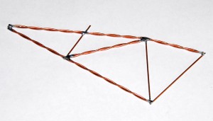
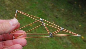
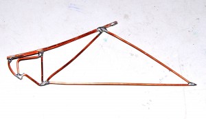
So how does the technique work? In short, you build a replica of the structure by soldering together copper wire. You then input the forces in the direction that they occur in real life, and watch what fails.
This is a truly brilliant way of assessing different designs. By closely watching the failure mode (eg Close to a join? In the middle of an unsupported length of ‘tube’? In compression? In bending? Failure by a gentle radius bend or sharp kink?) you can very quickly optimise and refine designs.
Complex, multi-tube designs that would normally need Finite Element Analysis computer software can be modelled in a short time – in some case, in minutes.
The modelling can be in two dimensions or in three. You can apply compression, extension, torsional and bending loads. You can model the affect of differing diameter (or wall thickness) tubes by altering the thickness of the wire, or by doubling the wire.
By photographing a full size mock-up, and then importing that pic into a PC and printing it out at much reduced size, you can take model tube angles and lengths directly from the print-out. In many cases, I actually build the model by laying the wire on the 2D print-out and soldering it in place in situ.
Forces can be applied by pliers with the model held appropriately by a vice or simple jig.
To see what you thought would be a strong design fail with the greatest of ease is an amazing wake-up call. To then make some (relatively) simple changes and develop a model that you physically can’t distort with the pliers is quite awesome, especially when you grab a piece of the bare wire and can bend it easily with just your fingers.
By juggling wire thickness and length, you can optimise the required strength of the individual tubes: they need be only as strong as required.
By weighing the model (or measuring the length of its individual ‘tubes’ and working out how much it would weigh if built for real) it’s possible to quickly assess if weight is going up more quickly than tested strength. Alternatively, by setting yourself a weight limitation, you can to develop the strongest design possible with that weight.
By inputting forces with springs it’s possible to accurately model the different magnitude of input forces – for example, on a model of a vehicle frame, placing twice as much braking force on the suspension member than the static weight force.
Of course, the copper wire model approach does not tell you how strong the overall structure is – it tells you how strong each part needs to be relative to the other parts. If you like, it quantifies the pecking order of required tube strength.
I have found this type of modelling to be an absolutely stunningly useful design tool.

 Julian Edgar, 50, has been writing about car modification and automotive technology for nearly 25 years. He has owned cars with two, three, four, five, six and eight cylinders; single turbo, twin turbo, supercharged, diesel and hybrid electric drivelines. He lists his transport interests as turbocharging, aerodynamics, suspension design and human-powered vehicles.


on February 17th, 2009 at 7:51 am
That is brilliant!
How did you work out what scale to make the model? Does 1mm wire representing 13mm tube need a 13:1 model?
The Uni WA Formula SAE make many full size models of their vehicle frame starting with rolls of cardboard, then plastic conduit, then mild steel, then chromoly. Mainly for packaging I think. I wonder if the two approaches (studying strength and 1:1 package) could be combined by using thicker wire?
on February 17th, 2009 at 9:02 am
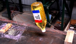
I made 1:1 models of some suspension designs – the pic of the model holding up the cooking oil container is 1:1.
I think it would be difficult to draw a relationship between the strength of the wrires in the model and the strength of the tube in the final deisgn. But the modelling clearly shows the ‘pecking order’ of required tube strengths, and their relative strength magnitudes.
on February 17th, 2009 at 10:37 am
Nice…
But would’nt it be easier to do it on a PC, they would have programs for this?
Maybe you can *loan* the PC/Program off a university
Good luck with your project, keep up the excellant articles and reviews
Cheers