Hi Liam…

Posted on October 21st, 2013 in Driving Emotion,Opinion,pedal power by Julian Edgar

Hi Liam,

Thanks for your questions. I hope my answers help you in your Year 11 design and technology studies.


Is designing a hobby, a source of income, or both?

My designing is both a source of income and a hobby. I enjoy doing what I do: if I can make it both my work and a hobby, so much the better.

Initially, I started out doing things just as a hobby, but then I realised that by simply describing (in pics and text) what I had done, and selling it as a magazine article, it could pay me money as well.


How long have you been designing things for?

I think I probably have been designing real things since I was about your age. In Year 11 I got an electric drill and then an electric jigsaw, and started building speakers systems and solar heaters.  My designs were thought-through, and then sketched on paper, before I started building. So they were projects that were designed – not just built as I went along.

I can remember designing things earlier than that – say, in Year 8 – but I never then actually made them, so I don’t think that counts.


Which part of design gives you the most satisfaction?

That’s a really good question – one that I have not thought of before.

I think perhaps the thing that gives me the greatest satisfaction is designing and building something that lots of people say will not work, or is stupid, or is a waste of time – then finding that it works really well.

When I designed and built my first suspension trikes, everyone who knew anything about recumbent trikes said things like: “Why would you bother – trikes without suspension ride fine.” Now, about ten years later, I see plenty of mainstream trike blogs and sites reviewing commercial suspension trikes and saying how great they are!

It’s both frustrating and rewarding – frustrating when I come up with something I think is great, and then (eventually) rewarding when people recognise years later that what I said was great, was in fact great!


What kind of projects do you most enjoy working on?

I think I most enjoy projects that involve vehicles – things you can pedal or drive on the road. I reckon that being in control of a moving thing that you designed and built (or even just modified) is the very best.

I also have designed and built electronic projects, pneumatic projects, speaker systems, solar heaters – and many other things… but I reckon that vehicles beat them all by a lot.


What has you favourite design project been so far? And why?

My favourite project is usually the thing I am currently working on.

So today I designed and started to build a trailer for my tractor lawnmower. It uses pillow-block bearings for the axle, hubs I machined on a lathe, and a 25mm RHS square tube frame, MIG welded together.

I have to do my “real” job tomorrow, but later in the week I want to finish the trailer, installing a steel deck and hardwood side rails.

I am also currently working on turbocharging my hybrid Honda Insight, and it’s been fun coming up with a water/air intercooler and new airbox for the car. I also made my own machine to place a lip on the intercooler tubes, to stop the turbo boost hoses blowing off under boost.

But this time last year, I was all excited about designing and building twin 15-inch subwoofers to put under the floor of my lounge room!

It’s good to be excited about whatever you are designing and building.


What’s the process you go through during a design project?

Here are my steps:

1. What functionality does the design need to have – what does it have to do?

2. What have other people done to address the same needs?

3. What aspects of their designs can I use, and what aspects can I develop that will better suit my needs and building capabilities?

4. What aspects from similar designs, but in completely different design areas, can I use? (So for example, when designing a stiff but light structure – what aspects from aircraft, from yachts, from airships, from skateboards, from bicycles, from rockets can I incorporate in my project?)

5. Can I build my design with my skills, money and workshop equipment? If not, how can I change it?

6. Now it’s time for sketches – lots of them.

7. Build the thing.


What’s the process you go through when building it?

1. Follow sketches

2. Any design changes that I decide to implement during the build, I re-sketch and then consider very carefully before doing.


On average how long will a design project take? From the initial concept to a finished design.

A really big project, like my three recumbent suspension trikes, perhaps 9 months to a year for each of them. My turbocharging (and intercooling, and fitting programmable engine management, and fitting a MoTeC dash, and full tuning, and tweaking the electric control system, and fitting a new HV battery pack) to my Honda Insight I’d expect to take 9 – 12 months.

I am a slow worker and will make a part again if I am not happy with the first version.


What are your preferences or priorities in terms of things like: form, function, durability and build-ability?

Form: I don’t consider aesthetics (how pretty it looks) much at all. Good design has an elegance and beauty of its own.

Function: is critical – it must perform.

Durability: in the sort of things I design and build, I look at durability in two key areas. These are high quality bearing surfaces (eg use of ball bearings), and fatigue strength (over-engineering to stop fatigue failures).

Build-ability – very important – I have to be able to build the thing (or use others only very sparingly).


When starting a design project do you prefer to start with a clean sheet or start from what others have done?

I like starting with a clean sheet and only then looking at what others have done. Sometimes I learn a huge amount by looking at others have done – other times, I think my ideas are better.

But always consider first what you want to do and only then look at what others have done.


Do you use computer modelling when working on a design project? 

The only computer modelling I use is in the design of subwoofers – I don’t use any other computer aided design at all.  This is mostly because I am very old, but also because I seem to better develop my ideas by:

1. Sketching – drawing ideas as I am thinking them up.

2. Making small models – that show (through destruction testing) how strong they are, where any moving parts will hit each other, etc.

3. Making rough versions and seeing how good they are before building the proper one. That’s especially the case in electronic and pneumatic systems.

I think if I were starting now I would be particularly interested in getting good skills in CFD (computational fluid dynamics – how fluids like air pass over objects), and CAD – computer aided design, especially in the stressing of parts.


What have you found to be the critical elements in the design of a HPV to meet your particular goals/needs?

One critical element in designing a suspension HPV (Human Powered Vehicle) is to use the lightest approach to achieving the outcome that you want – and you should be striving for an outcome where the suspension natural frequency is about 1Hz (for an explanation, see http://www.autospeed.com/cms/article.html?&A=112279).

If the suspension is sufficiently soft to absorb bumps, you then need very effective anti-roll capabilities to stop excessive body roll on corners.

Another critical element is to optimise steering – this is because the rider gets most of their handling feedback through the steering response and behaviour. Optimising this includes Ackermann, caster and trail.

But to make it all really simple – the HPV should always behave as the rider expects. Actually achieving that is incredibly difficult.


How do you decide when a design is finished e.g. is the HPV project finished or just on the back burner until you can implement another set of ideas? 

I finish one HPV project and start another when I think that starting from scratch is a better way of pursuing the next set of ideas.


To finish, do you commercialise you designs in any other way than publishing them in articles? 

i.e.

o   Protect any intellectual property you develop?

o   Keep secret particular problems or solutions you have found?

o   Look at production of your design?


I have looked at doing all those things and have decided that it’s best for me if I just write (and photograph) my designs and run them in paying publications. I also always tell it like it really is – not trying to hide any problems or solutions.

Commercialising a new design requires lots of risk in terms of money, and the further ahead of the other competitors that the design is, the harder it is to get it accepted.

Regards,
Julian Edgar
  • » Comments Comments Off on Hi Liam…

Better bike lights

Posted on November 13th, 2011 in Opinion,pedal power by Julian Edgar

We’ve previously covered in AutoSpeed building your own high quality bike head- and tail-lights. For my money the best design of DIY headlight was the one covered here  – it’s super-bright, has a broad beam that has excellent penetration, and is durable.

However, there have been two problems will all the light systems we’ve covered: the control electronics, and the battery.

To efficiently run high intensity LEDs you need a DC/DC converter that maintains LED current as battery voltage falls. Furthermore, an indication of battery level is important. Finally, it is best if flashing and steady modes are available. Doing these things with DIY electronics is of course possible (and we’ve previously covered some techniques for making your own) but the end result adds up in cost and size.

And batteries? To build your own pack that’s waterproof and compact is a harder ask than it first sounds – and then, what about a charger? In fact, I’ve tended for my own systems to go back to heavy and relatively inefficient sealed lead-acid (SLA) batteries – despite their size and weight, they’re easy to charge and come pre-packaged.

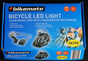
But things are rapidly changing. The other day I bought from Aldi (and unfortunately they’ll almost certainly all be gone by the time you read this) a bike headlight system.

It comprises a 3W LED headlight, 2 amp-hour lithium battery pack, mains-powered charger and assorted brackets for mounting the lights and pack. The system has switchable full power, half power and flashing modes. A battery level indicating LED is also fitted.

I have been watching bike lighting systems very closely for years, and I can say with some confidence that a year ago, a system just like this would have cost well over AUD$100.

The Aldi price? Originally $30 and on special at $20!

I bought one set and tested it. Then, on the basis of those tests, I went back and bought another four sets!

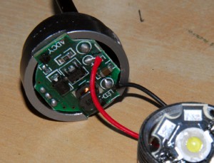
The real beauty of the systems is that the headlight can be easily pulled apart. Doing this reveals the use of a standard ‘star’ (eg Luxeon or Cree style) LED. In turn that means the LED can be changed to whatever colour you want – so in one system I have swapped-in a red tail light LED. (Bright? You’d better believe it!)

The smart LED control electronics can also be easily wired to a non-standard light. So I use one system to power the original glass-and-stainless steel 3W headlight I built in the story referenced at the beginning of this piece.

Are the results good?

Especially with some modifications, for the price I think they’re unbeatable.

A seminal paper… published in 1956

Posted on November 2nd, 2011 in automotive history,pedal power,Suspension by Julian Edgar

Back here I described my search for the lightest possible springs for a lightweight human-powered vehicle. Although I didn’t say so at the time, it had been my desire to use rubber – light, cheap and readily available.

However, as that article describes, I found it impossible to find a rubber (or elastomer) approach that allowed high spring deflections without overstressing the rubber. High suspension deflections were possible with rubber, but in turn that required high motion ratios (ie leverage) that resulted in large stresses in the suspension arms and spring seats.

However, since writing that article in 2007, I have been reading everything I can find on using rubber as suspension springs – and I have to tell you, there’s not a lot around.

But today I found a paper that I think is worth sharing with you. I can’t share the content – it’s copyright – but I can say it’s the best treatment of using rubber as vehicle springs that I have seen. It was published in 1956 and the author is Alex Moulton, the man who later developed the rubber springing used in the Mini, and the rubber-and-fluid suspension used in the Mini, Austin 1800, Morris 1100 and other vehicles.

You can buy the paper from the Institution of Mechanical Engineers Proceedings Archive here – it will cost you US$30.

If you are interested in lightweight vehicles with sophisticated suspension design, I think it’s a must-read.


Doing a lot with a little

Posted on September 10th, 2010 in pedal power by Julian Edgar

I’ve written before about the fundamental challenge of human-powered vehicles – whether they’re conventional bicycles or unconventional recumbent two or three wheel machines. And what is that challenge? It’s the limited amount of power available to push the vehicle along.

Everything about the machine needs to be designed to operate within this finite power paradigm.

Unlike say a car, where the answer to bad design is to simply add more power to propel the extra weight or overcome the extra aerodynamic drag, on a bike you cannot take that easy route. Thus a bike is the most efficient means of transport ever developed. That is, it uses less power to move you than any other approach – even walking.

Part of that development has been the engineering of efficient gear systems. Unlike in a car, where rear wheel dyno figures often show a 30 per cent power loss between the flywheel and the road (that power loss made up of inefficiencies in the gearbox and differential, and the flexing of the tyre over what is usually a pair of small diameter rollers), in a bike the gearing system losses can be measured at being less than a few per cent. That is, often 98 or 99 per cent of the rider’s power is transmitted to the back wheel. And with the use of relatively large diameter wheels and high pressure tyres, the amount of power transmitted to the road is scarcely less.

All bikes use at least one system of gearing – that created by the different sizes of the front and rear chain cogs. But most bikes use a more sophisticated system than this – variable gearing, achieved by either an internally geared rear hub (eg a 3-speed hub) or derailleur gearing, where the chain is forced to move to a different sized front or rear cog. Derailleur gear systems are more efficient than planetary-based internally geared hubs.

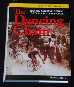
Recently, I read a brilliant engineering book on bicycle gearing. Called The Dancing Chain, it is subtitled: History and Development of the Derailleur Bicycle. However, it is much more than that, covering gearing systems from the very first bicycles to current machines.

Written by mechanical engineer Frank J Berto, the large and detailed book (more than 1000 diagrams over its 400 pages!) reflects the author’s 35+ years of writing about bicycle gearing and a clear life-long interest in bicycles in general.

I found it a fascinating read, able to be perused on all sorts of levels – from reading it as a technical history of a specific engineering innovation, right through to gaining practical advice for current cyclists.

Despite being the ‘updated and expanded’ edition, the book has several major typos and in part needs better editing. It’s also not cheap – but I highly recommend it.

The Dancing Chain, History and Development of the Derailleur Bicycle, Frank J Berto (and contributing authors), 2009, ISBN 978-1-892495-59-4

(The Dancing Chain was purchased for this review)

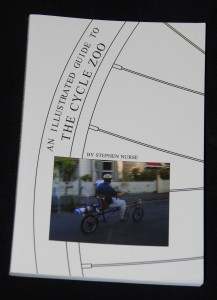
And if you’re interested in bicycle design, another book worth checking out is An Illustrated Guide to The Cycle Zoo, a self-published book on alternative bike design by another mechanical engineer, Stephen Nurse.

A paperback of about 120 pages, the book covers alternative bikes that arguably can give much better on-road results than traditional upright, diamond-framed machines – recumbent bikes, trikes and tandems.

Read the book as a detailed guide to these machines and it can be a bit frustrating, but read the book as a sourcebook of ideas, information and diagrams and it’s much more satisfactory. Stephen is to be congratulated for writing and publishing a book on a topic so seldom covered, but for anyone heavily into these machines the book will be a bit simple, and for anyone just wanting to learn about what these types of bikes can do for them, the book assumes a bit too much knowledge!

But if for example you’ve read in AutoSpeed about our recumbent pedal trike designs and would like to learn a bit more about these alternative forms of human-powered machines, it’s worth a read.

An Illustrated Guide to the Cycle Zoo, Stephen Nurse, 2009, ISBN 978-1-921488-08-5

(The Cycle Zoo was supplied by the author free of charge.)

Absorbing bumps

Posted on June 21st, 2010 in Opinion,pedal power,Suspension by Julian Edgar

The ability of a wheel to move backwards when it hits a bump is a very important ingredient in gaining good ride quality. The movement is accomplished in car suspension systems by the use of rubber bushes; many have asymmetrical voids within them to allow this type of tiny backwards movement without adversely impacting on bush stiffness in other directions.

But what about in a machine that requires suspension pivot points that can’t cater for this movement, ie those that need non-flexible pivots?

In a two wheel machine, especially one that is very light in weight, a leading arm suspension can be designed that will achieve this.

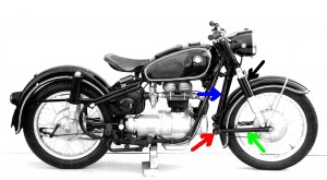
Leading arm suspension systems have been used in commercially produced motorcycles (eg the Earles forks) utilised by BMW in the 1950s, and shown here.  Note that the springs/dampers do not locate the suspension in any way, instead, the leading arms (green arrow) are pivoted at the point shown by the red arrow. The “forks” are indicated by the blue arrow and the springs/dampers by the black arrow.

A leading arm design of this type has anti-dive under brakes built in; as the braked wheel tries to keep turning, it pushes up on the pivot point, so counteracting the weight transfer forwards. In fact, some Earles machines are known to rise at the front under brakes.

But how does this front suspension design allow a movement backwards when the wheel hits a bump? As shown in the BMW design, it doesn’t – or at least, not much.

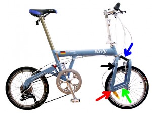
But as shown in the design of this bike, it does. Again the green arrow points to the leading arms, the red arrow to the pivot point, the blue arrow to the spring/damper and the black arrow to the forks. Note how the pivot point is low and so the wheel clearly moves backwards as it rises.

The bike is a Birdy folding machine and the front suspension travel is only about 15-20mm. I recently bought one and I am amazed at how well the front suspension works, especially given its minimal travel. It’s not effective over large bumps but it works brilliantly at removing vibration and harshness.

It’s also a particularly interesting design because in many suspension types, building-in anti-dive geometry actually causes the wheel to move forward as it moves upward, so making bump absorption worse rather than better. That’s not the case with this design.

More on lights

Posted on May 31st, 2010 in Opinion,pedal power by Julian Edgar

Regular readers will know that I like riding pedal-powered machines (conventional bikes, folding bikes and recumbent trikes) and that I very often ride at night.

Over the years I have developed my own high-powered LED head- and tail-lights, stories that have been covered in AutoSpeed. (For example, see the series starting here.)

However, in technology nothing stays the same and so about a year ago I started closely checking out the new wave of LED headlights designed primarily for mountain bike use. Living near Canberra, perhaps the Australian home of serious mountain bikers, I soon discovered shops selling LED lighting systems costing anywhere up to AUD$500. These typically used multiple 3W and 5W LEDs, lithium battery packs and trick circuitry to maintain light brightness and protect the batteries from full discharge. Different flash and power modes are also available.

In the shop these lights looked excellent, and attending a 24 hour mountain bike race showed how effective these top-line lights are in real-world conditions.

But, hell, $500…

So I decided to take a punt on eBay, buying a light that uses three Cree LEDs in a cast alloy housing, a lithium-ion battery pack and a dedicated charger. All for about AUD$100 delivered.

First impressions were very favourable, and I mounted the light permanently on my Brompton. Riding out into country south-central New South Wales, where the roads have no lighting and quite often there’s no moonlight as well, I found the light excellent in reach, spread and beam pattern. In fact, have the headlight aimed even fractionally high and on these country roads oncoming drivers kept flashing their headlights at me!

But then things started going downhill. Firstly, I was out at night, and a fair way from home, when the light extinguished itself. No warning, no reduction in power – just from full brilliance to off. Luckily I also run a light on my helmet so I could turn that on and get home. The problem? The battery voltage was low and when this happens, the light simply switches off. OK, so charge the battery up again and monitor how many hours of light are available – about 3 hours in fact.

But then a few weeks later I found the same problem occurred – great light then, bang, nothing. And the ‘run’ time was getting shorter and shorter.

On that occasion I found the AA cells in my helmet-mounted light were also getting low, and in addition to the darkness, there was fog. It was a dangerous ride home.

During this time I was running a rear Cateye red flasher, in fact a AUD$50 tail-light with six large, high intensity LEDs. It’s a good tail-light but it has a problem common to many: it’s quite directional and so if not mounted exactly right, visibility to car drivers falls off rapidly. Plus, despite having eight different flash modes, none was all that effective.

Mulling over all of this, I decided to dig out my previous home-made lights and rig up a new lighting system. I wanted:

  • Excellent front lighting – at least subjectively 75 per cent as good as the Cree x 3 system
  • Much better rear lighting, with more range and vastly better off-axis brightness
  • A great ‘run’ time
  • Some indication that the battery was getting low in charge
  • Little effort and no new cost outlay

So I dug out my front headlight, made from a stainless steel drinking cup, a 3W Luxeon LED and collimator, a heatsink and a 75mm magnifying glass. The tail-light I selected from my odds and ends box uses another stainless steel drinking cup, a lens salvaged from a camera, a red 1W Luxeon LED and another heatsink. (Both lights were covered in the previous series.)

I have a bunch of 12V Sealed Lead Acid batteries I’ve previously salvaged from discarded uninterruptible PC power supplies, and a home-made battery charger detailed here.

I added the Pulser  module and used simple ceramic resistors to regulate the LED currents.  I then added a diode and a handlebar-mounted switch so that I could easily operate the headlight in flashing or steady modes. The Pulser is set for a 3Hz flash rate with 12 per cent duty cycle.

It’s a relatively simple system that is also heavier than the professional approaches. But it’s also a system that has heaps of duration (something like 5 hours should be easily achieved, night after night if necessary), provides better overall safety than the previous system, and cost me nothing much to make. It also shows, by the very simple indicator of declining light output, when it needs to be recharged.

Kinda back to the future – something that on paper looks inferior but for me, works far better.

Finding Suspension Roll and Pitch Centres

Posted on January 21st, 2010 in Opinion,pedal power,Suspension,testing by Julian Edgar

The trouble with suspension roll centres is that they’re often rather obscure in concept, let alone in location.

In this article I tried to simplify the concept of roll centres, largely by using geometric drawings.

(So what actually is a roll centre? It’s the imaginary point about which the car rolls. The front and rear suspension roll centres can be at different heights above the ground [but always on the centreline of the car] and on different vehicles the heights can vary from being above the ground, to at ground level, to below the ground.)

Normally roll centres are located by careful drawings of the suspension, a prerequisite being that you need to know the exact location of suspension pivot points, lengths of suspension arms and so on.

roll centre

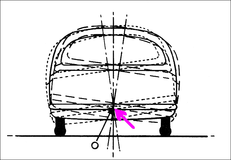
However, as shown in this diagram, the roll centre of an existing vehicle can be located by directly measuring the way the car behaves. If the car is physically rolled from side to side, there will be one point that never moves (or moves only minimally). That’s the roll centre. If multiple photos are taken of the car in end-view, this point can be easily located. 

This is a very useful technique – you can locate the roll centres for either the front or rear suspension, and no difficult measurements of the suspension geometry need be made.

And it’s not just the roll centre(s) that can be located in this way. In addition to roll, cars pitch – that is, the front dives and the rear rises, or vice versa. This occurs not only under acceleration and braking, but also over bumps in the road. The amount of pitch – or, more precisely, the pitch accelerations – are a major determinant of ride quality.

So how do you find the pitch centre? A book I have – Fundamentals of Vehicle Dynamics by Thomas Gillespie – devotes a number of pages of mathematics to locating the pitch centre of a car. However, as with the roll centre, pitch centres can be found by direct measurement.

I did this the other day for my recumbent, pedal, suspension trike. I am doing a lot of work on its suspension, including measuring real-time pitch accelerations over bumpy surfaces. After making a host of measurements of these accelerations, I thought I should find where the pitch centre actually is.

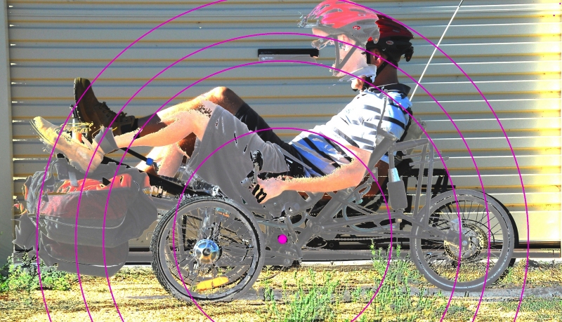
I had two photos taken of the trike (with me on it), both in side view. In one pic, the front suspension was at max extension and the rear in max compression. In the other pic, the suspension extensions were the other way around. (I use air suspension and for this test I interconnected the units front to back, so giving zero resistance to pitch. To get the front to adopt max compression, I added some weights.)

I then overlaid the pics, playing with the image until I could find a point around which the trike body was rotating in pitch. This was best shown by placing radii centred on that point – the circular lines intersect with the same part of the trike in both pitch extremes. (It’s harder to explain than it is to do!)

trike pitch centre

In this pic, the pink dot is the pitch centre. As can be seen, the greatest mass on the machine (that’s me) is located above the pitch centre. Furthermore, a lot of that mass is located a fair way from the pitch centre, increasing the pitch moment of inertia. This is one reason that over rough ground, the pitch accelerations of the machine are very low.

Talking about moments of inertia in pitch is taking it a further step in complexity. But back to ‘centres’ –  if you’re grappling with the suspension design of a custom vehicle, it make things a lot clearer when you can so easily locate not only the roll centres, but also the pitch centre.

  • » Comments Comments Off on Finding Suspension Roll and Pitch Centres

Are all deflections bad?

Posted on May 5th, 2009 in electric,pedal power,Suspension,testing by Julian Edgar

One of the automotive ideas that seems to be taken as gospel is that the chassis and suspension arms should be stiff – that is, neither should deflect when subject to load. In fact, if I’d had a dollar for every time I’ve read that ‘good handling depends on a stiff chassis’ I’d be richer than I am.

But I think that, especially for ultra-light vehicles, this notion is simplistic.

Firstly, every structure deflects under load. That deflection may be small, but it occurs. Even the Sydney Harbour Bridge has an allowable deflection under maximum load of 4.5 inches (114mm) in the centre of its span.

Secondly – and more importantly – chasing reduced deflection will add substantially to weight. The corollary of that – the lightest possible vehicle will always have deflections.

Finally, not all deflections are bad.

Let’s start off with the last. Most cars use rubber bushes that are designed to have differing stiffnesses in differing planes. One reason for this is so that wheels can move fractionally backwards when they meet a bump, reducing harshness. Another reason is that in some (many?) suspensions, if the bushes didn’t have ‘give’, the suspension would lock up solid during travel.

Passive steering suspension systems – the first well publicised was the Porsche ‘Weissach’ axle of the 928 – often use bushes that deflect, or links that give an effectively ‘non-stiff’ suspension in some planes.

Going backwards to the second point, getting rid of measurable deflections in chassis and suspension arms will result in a major increase in weight. In ultra-light vehicles (eg those powered by human legs, a small petrol motor or an electric motor), and especially those made from chrome moly steel tube, deflections under major loadings are often able to be seen by eye.

For example, the peripheral torsional wind-up of a front suspension arm might be 5mm or more under maximum braking, and under max cornering there might be 3 or 4mm of bending in wheel supports. In a human powered vehicle (HPV) with a recumbent seat and front pedals, boom flex under maximum pedalling force can often be 10mm or more.

So does all this matter? In some cases (like boom flex, that subtracts from the power available from the rider), yes it does.

But in other cases – not necessarily.

What is required is that the structure is never stressed to the point of failure, and that the vehicle dynamics remain consistent.

I have been musing over these ideas in the context of the HPV I have been building.

I know that under brakes the beam front axle will torsionally wind-up, reducing the static castor of the front, steering wheels. That might lead to steering dartiness under brakes – but for the fact that when the front brakes are in action, the vehicle has some dive, that in turn causes a rapid increase in castor.

On my previous recumbent trike design (called the Air 150), I had difficulties in getting rid of steering twitchiness. The problem felt all the world like toe-in bump steer, where I’d put on some steering lock, the machine would roll slightly – and the outer wheel would toe-in, giving a sharper steering response than requested. That was the theory – but I found this odd when on the workshop floor, toe-in on bump was small or non-existent.

But I now wonder if the outer semi-leading suspension arm wasn’t flexing sideways a little with the sudden application of the lateral force, which in turn caused “turn-in steer” as the suspension arm and the steering tie-rod flexed through different arcs.

Certainly, at the very early stage of testing I am at with my current HPV ‘Chalky’, there’s no steering twitchiness on turn-in – and the front suspension is laterally much stiffer than the previous design.

(I fixed the Air 150’s twitchiness by setting the suspension up with either static toe-out, or toe-out on bump – but the problem returned when carrying really big loads. If the arms were bending laterally, perhaps it just needed even more static or bump toe-out to compensate?)

And I guess that’s the point. In a vehicle – any vehicle – there will be dynamic variations that don’t match the static settings.

(Many years ago, I remember having a wheel alignment done on my Daihatsu Mira Turbo. I was happy with the alignment machine’s read-outs – but then the mechanic got me to sit in the driver’s seat. On that simple car, the suspension settings immediately changed!)

If the weight of the vehicle has been has to be kept to an absolute minimum, and so major deflections occur in the suspension and frame, the trick is to optimise the direction of those deflections so that they don’t subtract from – and possibly even add to – the on-road experience.

That’s a very different notion to ‘keep everything as stiff as possible’.

How utterly stupid they are

Posted on April 28th, 2009 in Opinion,pedal power by Julian Edgar

As with any recreational pursuit, cyclists come in sorts of shapes, sizes and special interests.

I’m interested in heavy recumbent touring pedal machines; my neighbour – a man in his sixties – likes traditionally shaped ultra-lightweight racing machines.

Each morning his car heads out, bike on the rear rack, to allow him to get in some cycling before work.

He rides with a like-minded group who sprint (well, in my terms it’s sprinting!) at 35 km/h or more on the flat roads of the Gold Coast.

Then, a few days ago, he abruptly stopped his morning rides. A broken shoulder blade, multiple abrasions and concussion will tend to do that.

He’d been out with his mates, riding fast to catch up with a breakaway group ahead. He reached the rearmost person and leaned over to pat him on the back. He doesn’t know what happened next – perhaps he startled the other rider who swerved, or perhaps at just the moment he took one hand off the handlebars the very narrow front racing tyre fell into a groove in the road.

But whatever the cause, when he regained consciousness he was lying on the road, in pain and with the greatest of desires to get the hell out of there and to safety.

The cycling group helped him, and it wasn’t long before he received medical help and then, subsequently, was home.

His injuries are certainly not trivial, but it could have been much worse: he could have been dead.

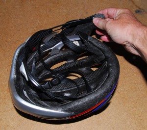
The short loss of consciousness and the concussion indicate that his head hit the road. So does the state of his helmet….

The helmet is destroyed.

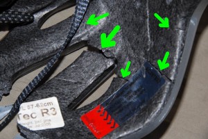
A piece of the foam has broken right away…

…but what’s even more interesting is that the foam is cracked in multiple places. In fact, there’s barely an area of the helmet that doesn’t have large or small cracks in it.

To look at it makes me feel slightly ill: without a helmet, those cracks would probably be in my neighbour’s head.

The helmet did its job in just the way it was designed to.

I look at riders – often young – who don’t bother wearing a helmet and think of how utterly stupid they are…

It’s not in the texbooks…

Posted on April 23rd, 2009 in Handling,Opinion,pedal power,Suspension by Julian Edgar

I am not certain it will happen: I hope so.

As time has passed, the development of ultra light-weight vehicles has become a more important theme for AutoSpeed (and this blog). It’s rather like our longstanding acceptance and enthusiasm for hybrid vehicles: it’s a change in transport architecture that simply makes sense.

(Of course, ultra light-weight vehicles have existed previously – especially just post-World War II with the German and British three wheelers. But over the last 50-odd years, there have been almost none produced.)

So what do I hope will happen? The development of an increasing number of such machines.

If that occurs, especially on an individual constructor level, then people will face some unique and very difficult problems.

We tend to take for granted developed automotive technology, and to see engineering solutions only within that paradigm. But when it comes to ultra light-weight vehicles, that’s simply wrong.

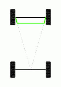
For example, take Ackermann steering – that’s where when cornering, the inner wheel turns at a sharper angle than the outer wheel, resulting in no tyre scrubbing. If I was to say that I have spent the last three days struggling with Ackermann steering, some people would laugh.

“It’s all in the books,” they might say, “just angle to the steering levers inwards like this diagram shows. Been done a million times. Next problem?”

But you see, that solution largely applies only if steering like a car is used – with a steering box or steering rack.  And, for ultra lightweight vehicles, both steering boxes and steering racks (or, any currently available, anyway) are way too heavy. 

So, how do you achieve Ackermann steering without a steering box or steering rack?

Australian recumbent pedal trike manufacturers Greenspeed have some brilliant solutions. (Disclaimer: my wife sells Greenspeed trikes.)

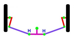
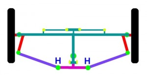
One of their approaches looks like this (the drawing is not to scale.) The system uses wheels that turn on kingpins, two steering tie-rods, and one central linking member turning on an offset pivot. The steering is by handlebars; these connect at the points marked ‘H’ and have a motion that is a combination of both sideways and fore-aft.

This steering system achieves full Ackermann compensation, and requires only four rod-ends and one pivot point. (These are in addition to the two kingpin pivots.)

That is simply an incredibly light and effective steering system.

I recently spent day after day coming up with alternative steering systems for my recumbent pedal trrike – and then building them. It’s quite easy to end up with steering with two kingpins, six rod-ends and two pivot points – typically, about 50 per cent heavier than the Greenspeed system!

Making things more difficult for me was that, unlike the Greenspeed trikes with the above steering system, my design uses long-travel suspension. And, getting rid of bump steer (ie toe changes with suspension movement) is another nightmare.

Again, people will be thinking only in an automotive paradigm.

“Bump steer? That’s easy – just set the length of the tie-rod so that it’s the same as the distance between lines drawn through the upper and lower ball-joints….” (and so on).

Trouble is, my suspension system doesn’t even have upper and lower ball-joints… Instead, it’s a leading arm, torsion beam, dead axle with a Watts link.

Shown here is (another) rough diagram. In fact, this is pretty well how my system is with Ackerman compensation and zero bump steer. (The really knowledgeable amongst you will have picked a slight error in the drawing.)

The point is that none of this design can take lessons straight out of textbooks – especially automotive textbooks. Of course, the fundamental elements (like the Watts Link, the concept of Akermann steering correction and so on) are all well documented, but in unique applications, actually applying those ideas is another thing entirely.

I am not setting out to suggest I am some kind of hero – all the designers of solar race cars and pedal-powered tadpole trikes have tackled the same ground. But what I am saying is that the challenge is massive, that achieving a good outcome in terms of suspension and steering dynamics – all at a weight that is less than just the steering wheel of a normal car – is difficult beyond belief.

Ackermann and bump steer? If it’s in a typical car textbook, in this class of vehicle it’s usually not the solution…